Inverted Planetary Roller Screw vs Rotary Joint Modules: Humanoid & High-Payload Sourcing Guide
Compare inverted planetary roller screws vs rotary joint modules for humanoids: load, linkage, fatigue life and RFQ checks. Plan your engineering review.
Inverted planetary roller screw vs rotary joint modules: choose a linear IPRS actuator when the linkage can meet thrust, stroke and speed requirements across the full joint travel. Choose a rotary module when output-axis packaging, angular travel and simpler joint kinematics matter more. Neither architecture is automatically safer under impact or more efficient over a walking cycle.
This guide helps engineering leads and procurement teams compare robotic joint modules for humanoids, quadrupeds and high-payload manipulators. Use the decision matrix and RFQ checklist to request comparable supplier evidence, then validate the installed axis.
Published and reviewed: October 27, 2026. Scope: Global sourcing, English-language engineering guidance. The method combines transmission equations, explicitly assumed sizing examples and supplier-document checks. Examples are reproducible calculations, not measured actuator results or customer case studies. Ratings, delivery times, prices and safety suitability remain model- and application-specific.
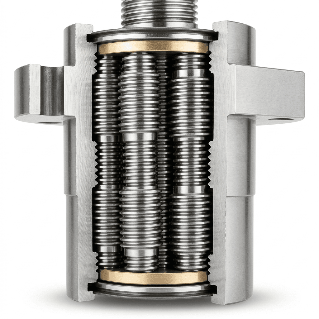
The lead image is a roller-screw cutaway illustration; it does not establish a supplier model, dimensions or a qualified load rating.
For a candidate list, start with our robotic joint module product families. If you already have a duty cycle, request an engineering and RFQ review with the assumptions listed below.
1. Executive Summary & Sourcing Decision Matrix
Compare both candidates at the same joint torque, speed, ambient temperature and duty cycle. A screw's axial load rating cannot be compared directly with a module's output torque rating.
| Engineering & Procurement Dimension | Inverted Planetary Roller Screw (Linear) | Rotary Joint Module | Sourcing / Specification Impact |
|---|---|---|---|
| Primary Motion Output | Linear thrust and stroke | Angular torque and speed | Convert both to the required joint load and motion. |
| Transmission | Threaded rollers transfer load between screw and nut | Strain-wave, cycloidal or planetary reduction, depending on model | Confirm the actual mechanism and supplied assembly boundary. |
| Shock Load Capacity | Depends on screw, support bearings, rod, mounts and load path | Depends on reducer, output bearings and housing | Request allowable peak, emergency and repeated loads with duration and cycle count. |
| Effective Lever Arm | Joint torque varies with the perpendicular moment arm | No external linear linkage conversion at the output flange | Sweep the full travel; identify singularities and stops. |
| Mass Distribution | Can move motor mass toward the torso or hip | Often mounted at the joint; remote mounting is also possible | Compare complete moving assemblies, including linkage and bearings. |
| Side Loads | Must remain within the assembled actuator's published radial and moment limits | Integrated output bearings may carry external loads | Require a combined-load bearing check for either candidate. |
| Backdrivability & Compliance | Lead, preload, friction, seals and motor inertia all matter | Ratio, reducer friction and motor inertia all matter | Measure breakaway force/torque and force-control response. |
| Rigidity & Lost Motion | Includes screw, supports, rod ends and linkage | Includes reducer, output bearing and housing | Specify load, position, temperature and measurement method. |
| Thermal Duty | Motor, nut, bearings and lubricant set limits | Motor, reducer, electronics and lubricant set limits | Compare stabilized continuous output under identical cooling. |
| Commercial Scope | May require separate guides, joints, brake and feedback | May integrate bearing, drive, feedback and brake | Normalize the BOM, validation scope, warranty and spare-parts terms. |
2. Mechanical Architecture & Working Principles
The Inverted Planetary Roller Screw (IPRS) Mechanism
Planetary roller screws use threaded rollers to transmit load between a screw and nut. Inverted designs rearrange the threaded members and roller travel to suit compact actuator packaging. The Rollvis product overview distinguishes planetary, inverted, recirculating and differential screws; those labels do not establish interchangeable ratings.
One integrated arrangement drives a rotating nut with a motor while constraining the output rod against rotation. Other arrangements drive the screw or translate the nut. Request a section drawing identifying the rotating member, translating member, roller retention, anti-rotation guide and thrust-bearing load path. Direct motor integration is an option, not a defining feature of every IPRS assembly.
For a direct-coupled rotating member, a steady forward-motion estimate is:
F = 2π × η_forward × T_motor / lead
Here force F is in N, motor torque is in N·m and screw lead is in m/revolution. With assumed torque 8 N·m, lead 0.0025 m/revolution and efficiency 0.88, the calculated thrust is approximately 17.7 kN. At 1,800 rpm, ideal linear speed is 0.075 m/s. These are separate operating assumptions: the motor must actually deliver the required torque at that speed.
This calculation excludes acceleration, preload drag, seals, buckling, support-bearing limits and thermal derating. It establishes neither continuous thrust nor a mass or packaging advantage over a ball screw or gearbox.
Engineering Visualization: IPRS Linear Actuator vs. Rotary Harmonic Joint Module
Figure 1: Conceptual layouts, not supplier CAD or tested hardware. Left: one rotating-nut arrangement with a translating rod. Right: a strain-wave rotary reducer; cycloidal and planetary modules use different mechanisms. Scroll horizontally on small screens to read the labels.
3. Deep-Dive Comparison: Five Critical Engineering Trade-offs
1. Contact Mechanics & Shock Load Survival
Roller screws distribute load through multiple threaded contacts, but contact stress depends on local geometry, alignment, preload and load sharing. Ball screws and geared rotary modules can also survive shock when correctly sized. No topology eliminates indentation, fatigue or overload damage.
For an impact event, record the joint torque or actuator thrust waveform, rise time, pulse duration, repetition count and joint position. Map the joint load through the actual linkage before checking the screw, rod, support bearings and mounts. Compare rotary candidates against their specified repeated-peak and emergency-stop torque limits; these are different limits.
Procurement rule: Accept an impact claim only with a load case and a documented acceptance test. Ground acceleration alone cannot establish internal actuator force or a universal safety factor.
2. Kinematics & The Variable Lever-Arm Effect
For a planar linkage, joint torque magnitude is τ_joint = F_actuator × r × |sin(α)|, where r is the pivot-to-attachment distance and α is the angle between that radius and the actuator force. Equivalently, the perpendicular moment arm is r_eff = |dx/dθ| and |τ_joint| = |F_actuator| × r_eff, with θ in radians. Linear speed magnitude is |v| = r_eff × |ω_joint| away from singular positions.
Illustrative linkage screening at 240 N·m:
| Joint Position | Assumed Perpendicular Moment Arm | Required Actuator Force | Force at a 1.5× Design Load |
|---|---|---|---|
| A | 60 mm | 4.0 kN | 6.0 kN |
| B | 40 mm | 6.0 kN | 9.0 kN |
| C | 20 mm | 12.0 kN | 18.0 kN |
These are assumed geometries, not measurements. The 1.5× multiplier illustrates sensitivity; it is not a prescribed safety factor. At position C, the earlier 17.7 kN theoretical thrust would already fall short of the assumed design load. If the actuator force line passes through the joint pivot, the moment arm tends to zero and finite actuator force cannot support a nonzero joint torque.
A near-straight knee can have either favorable or unfavorable leverage depending on attachment geometry. Rotary modules avoid this external linkage transformation, but available torque still depends on speed, voltage, temperature and controller limits. Use the actuator sizing and selection workflow to organize the load cases before comparing quotes.
3. Proximal Mass Distribution vs. Distal Inertia
For a point mass, inertia about a given axis is I = m × r². Moving an assumed 3.5 kg actuator body from 0.45 m to 0.15 m from the hip reduces that body's contribution from 0.709 to 0.079 kg·m², a calculated reduction of 0.630 kg·m².
This is not a reduction in total leg inertia: rod ends, linkage, guides, cabling and their motion must be included. A rotary joint at the knee is distal relative to the hip, while remote rotary transmission is also possible. Compare full-assembly CAD mass properties before predicting walking cadence or battery life.
4. Side-Load Sensitivity & Guide Integration
A screw transmission primarily carries axial load. The assembled cylinder may include a guide or rod bearing, but its permitted radial load and moment must be specified at the relevant extension. There is no universal allowable side-load percentage.
For a pivoting limb, use a mounting arrangement that accommodates the required articulation without overconstraining the cylinder: spherical joints, suitable clevises or other engineered pivots. For a guided carriage, verify guide alignment and load sharing. Include joint clearance, rod buckling, interference and end-stop load paths in the review.
An integrated rotary output bearing also has finite axial, radial and overturning-moment ratings. Request the combined-load calculation and required supporting structure rather than assuming the module replaces every external bearing.
5. Thermal Dissipation Pathways
Both actuator types reject motor, transmission and drive losses through their housings, mounts and surrounding air. A moving rod does not establish superior cooling; a rotary stator does not necessarily conduct its heat through the reducer teeth.
Require continuous force/torque at the intended speed, ambient temperature, mounting heat sink and cooling conditions. Run the representative duty cycle until thermal stabilization, logging winding, drive and transmission temperatures. Record peak duration and recovery time separately. Discuss power, feedback and bus requirements alongside the actuator integration guide.
4. Operational Lifetime Calculation: State the Supplier's Model
A dynamic axial load rating is a fatigue-model input, not a maximum instantaneous force or a service-life warranty. ISO 281:2007 concerns rolling bearings and basic rating life at 90% reliability. Its scope does not independently certify a complete roller screw actuator. ISO 3408-5 concerns ball screws; it must not be presented as a universal roller screw qualification method.
Basic Rating Life Formula & Boundaries
For a supplier model expressed as L10 = (C_a / F_eq)^p, L10 is in millions of revolutions, C_a is the dynamic axial rating, F_eq is the equivalent axial load and p is the supplier-confirmed exponent. Do not select p solely because the transmission contains rollers.
Under constant equivalent load and nonzero mean rotational speed:
L10_hours = 1,000,000 / (60 × n_mean) × (C_a / F_eq)^p
For a compatible variable-load model, F_eq = [Σ(F_i^p × ΔN_i) / ΣΔN_i]^(1/p), where ΔN_i is the absolute number of revolutions in each segment. This is a revolution-weighted load, not an arithmetic or automatically cubic time average. Confirm how the supplier handles reversals, short strokes, preload, reliability and lubrication corrections. Dwell time adds no revolutions but still requires thermal and static-load checks.
Reproducible Sizing Example: Hypothetical Humanoid Knee
Assume an already-derived equivalent load of 3,200 N, mean absolute speed 1,800 rpm and a target basic rating life of 10,000 operating hours. The corresponding travel is 1,080 million revolutions. Rearranging gives C_a = 3,200 × 1,080^(1/p).
| Assumed Supplier Model | Required C_a | Meaning |
|---|---|---|
| p = 3 | 32.8 kN | Conditional calculation if the selected catalogue uses this exponent and rating convention. |
| p = 10/3 | 26.0 kN | Sensitivity case only; not an ISO certification of this screw. |
At p = 3, a hypothetical C_a of 12 kN gives approximately 488 hours under the same constant equivalent load and speed. Changing a supplier's rating convention invalidates a direct comparison. Neither result guarantees field service life: wear, contamination, impact, seals, electronics and maintenance can govern replacement first.
RFQ decision: Request the model, exponent, rating basis, load spectrum and calculation worksheet together. Compare candidate ratings only after those definitions match.
5. Joint-by-Joint Allocation in Next-Generation Robots
The following is an engineering shortlist, not a verified bill of materials for any named humanoid OEM. Each row requires a full travel and load review; linear and rotary options can both be viable.
| Robot Anatomical Axis | Candidate Actuation Topology | Decisive Check |
|---|---|---|
| Knee Pitch | Linear IPRS or geared rotary module | Worst-position leverage, impact waveform and moving assembly inertia. |
| Ankle Pitch & Roll | Paired linear actuators or rotary modules | Coupled kinematics, actuator force allocation and fault behavior. |
| Hip Pitch | Linear linkage or rotary module | Squat-to-stand load, stroke, speed and packaging interference. |
| Hip Yaw & Roll | Rotary module or engineered linkage | Required angular travel, cable routing and bearing moments. |
| Torso / Waist Yaw | Rotary module | Combined bearing load, stiffness and cable-twist limits. |
| Shoulder 3-DOF | Compact rotary modules or remote transmission | Axis interference, thermal coupling and harness routing. |
| Elbow Flexion | Linear linkage or rotary module | Payload moment across travel and total forearm assembly mass. |
| Wrist Axes | Compact rotary modules or remote transmission | Payload, travel, backlash and cable pass-through requirements. |
| Dexterous Hand Fingers | Miniature screw or tendon transmission | Tendon routing, friction, sensor placement and maintainability. |
6. Two-Phase Sourcing & Quality Acceptance Checklist
Phase 1: RFQ Technical Specification Checklist (Pre-Nomination)
- Joint load and motion: Supply torque-speed-time traces, full angular travel, impact cases, payload and linkage geometry. Convert to thrust and stroke where appropriate.
- Manufacturing and accuracy: Specify lead error, lost motion and stiffness with measurement conditions. Request process evidence rather than rejecting all rolled or accepting all ground threads by label.
- Materials and heat treatment: Require a drawing-linked material specification, heat-treatment route, inspection locations and traceability. Through-hardening and case-hardening need different acceptance criteria.
- Dynamic and static ratings: Obtain the rating definitions, life exponent, reliability assumptions, preload treatment and allowable transient loads for the actual assembly.
- Mounting and external loads: Confirm guide, rod-end and support-bearing scope, rod buckling limits, tolerances and combined-load capacity.
- Feedback and control: Specify required installed accuracy and control bandwidth. Encoder resolution alone does not establish output accuracy; identify motor-side and output-side measurements.
- Thermal and stopping behavior: Agree ambient and mounting conditions, sensors, current limits, brake or counterbalance needs, power-loss behavior and peak recovery time.
- Commercial comparability: Request prototype and volume quantities, included drive/feedback/brake, Incoterm, destination, lead time, warranty, spare parts and change-control terms. Separate tooling and validation costs from recurring unit price.
Use the actuator price and cost guide to structure the commercial comparison. Keep unknown costs and lead times marked as pending supplier confirmation.
Phase 2: Factory Acceptance Test (FAT) & Incoming Inspection (IQC)
Agree model-specific thresholds before the sample PO. The methods below define evidence to collect, not universal pass/fail limits.
| Inspection Item | Test Method / Conditions | Acceptance Evidence to Agree |
|---|---|---|
| No-Load Drag | Sweep both directions over usable travel at specified speed and temperature | Recorded force/torque trace and allowed deviation from approved sample. |
| Lost Motion & Stiffness | Reverse a stated axial load or output torque at defined positions | Separate lost motion from elastic deflection; retain load-displacement curves. |
| Alignment & External Loads | Measure rod/guide alignment or flange runout and apply agreed combined loads | Drawing tolerances, instrument uncertainty and no binding through full travel. |
| Thermal Duty | Run the agreed load-speed cycle under specified ambient and cooling until stable | Temperature logs, continuous output and no unagreed thermal/current derating. |
| Impact / Overload | Apply the agreed waveform, repetition count and joint configuration on a protected fixture | Post-test function, lost motion and inspection meet documented limits. |
| Sealing & Lubrication | Test to the claimed ingress procedure and inspect lubricant condition | Report identifies procedure, mounting state, lubricant and maintenance interval. |
For system-level evidence ownership, review the actuator reliability and safety guide. A passed component inspection does not approve the complete robot application.
7. Frequently Asked Questions (FAQ)
Q1: Why can inverted planetary roller screws cost more than ball screws?
Internal thread geometry, matched components, preload, inspection and production volume can affect cost. Compare quotes at the same required load, life, travel, accuracy and assembly scope. No fixed price premium or lead time applies to every supplier.
Q2: Can an inverted roller screw be backdriven for impedance control?
Possibly. Lead, friction, preload, seals, motor inertia and any brake determine the result. Request measured breakaway force, reverse efficiency and dynamic response across temperature and load. Motor current can contribute to a calibrated force estimate, but friction and acceleration terms prevent it from being a universal contact-force measurement or independent safety function.
Q3: What failure modes should the sample test cover?
Contact fatigue, wear, lubrication loss, contamination, overload indentation, rod buckling, support-bearing damage and mounting misalignment can all matter. Synchronization components may also be vulnerable in designs that use them. Their relative likelihood requires design and duty-cycle evidence; there is no universal single dominant failure mode.
Q4: How do lubrication intervals compare with rotary reducers?
Use each manufacturer's approved lubricant and maintenance schedule, adjusted for load, speed, temperature, contamination and sealing. Do not assume a generic hourly interval or add PTFE/MoS2 without approval. Ask whether the supplied assembly is relubricatable and how maintenance changes under the intended robot duty cycle.
Q5: Can I mount an inverted roller screw rigidly without spherical rod ends?
Yes, when the mounting and guidance system controls alignment and external loads within the actuator's limits. A pivoting linkage needs the appropriate articulation, which may use spherical joints or suitable clevises. Verify all degrees of freedom and full-stroke interference; no joint style alone guarantees freedom from side load.
8. Sources, Specifications & Limits
Sources checked on October 27, 2026. These public pages establish product-family or standard scope; they do not substantiate measured performance of the products shown here.
- Rollvis: roller screw product families — Manufacturer overview distinguishing inverted and other roller screw designs and describing potential load/rigidity benefits. Obtain the selected model's drawing and rating worksheet before sizing.
- ISO 281:2007 — Rolling bearings: dynamic load ratings and rating life — Bearing-life scope and 90% basic rating reliability. This is not a standalone roller screw actuator certification; confirm the applicable edition and supplier calculation method.
- ISO/TS 15066:2016 — Collaborative robots — Scope for collaborative industrial robot systems and their work environment. It does not directly apply to non-industrial humanoids or establish actuator impact capacity. Confirm application-specific requirements with the responsible integrator.
9. Engineering Review & Technical Support
Choose from the complete load path: joint motion, linkage or reducer, bearings, mounting, feedback, thermal duty and stopping behavior. A mixed linear/rotary architecture is one option, with allocation decided by the actual robot geometry and validation evidence.
For a useful first response, send an engineering RFQ with payload, joint torque-speed-time trace, linkage drawing or joint travel, ambient/cooling conditions, supply voltage, control interface and prototype quantity. Ask for candidate drawings, a calculation with stated assumptions and a sample acceptance plan. Final ratings, availability and commercial terms require confirmation for the selected model.
Author

Categories
More Posts
Robot Joint Module OEM Selection Guide (2026)
A practical engineering and sourcing guide for OEM teams evaluating robot joint modules for humanoid, cobot, and mobile robot programs.

Permanent Magnet vs Spring-Applied Power-Off Brakes in Robotic Joint Modules: Holding Torque Density, Thermal Dissipation, Engagement Latency, and Fail-Safe Sourcing Guide
Compare permanent magnet vs spring-applied robot joint brakes for torque, heat, backlash and engagement time. Use the RFQ checklist to shortlist suppliers.
Hollow-Shaft vs Solid-Shaft Robot Joint Modules: A Sourcing Guide (2026)
An engineering and procurement guide to evaluating hollow-shaft versus solid-shaft robotic joint modules for humanoid, cobot, and industrial robot arms.