
Calculator + engineering selection guide
Actuator Module for Robots Sizing and Selection
Estimate joint load torque and mechanical power, then check the evidence needed to select a module. Start with the editable example below.
Sources reviewed · Preliminary screening; product capability remains unverified.
Four decisions before shortlisting a module
- Define the load at the joint output. Mass and speed alone do not establish torque; include geometry, acceleration and resistance. [S2]
- Separate load demand from actuator capability. Check the cycle against continuous and peak curves with their operating conditions. [S1] [S6]
- Choose gearing against the motion task. A fixed inertia-ratio cutoff cannot establish stability for every drive and mechanism. [S3]
- Compare measured properties. Zero backlash does not eliminate elastic deflection; a low-ratio research actuator does not validate every QDD product. [S4] [S5]
What the calculator does—and what remains unknown
This is a single-axis rigid-body screening model at the joint output. It adds positive load magnitudes as if they coincide. The envelope may overstate a particular motion segment, but omitted loads can still make it an underestimate.
Tgravity = m × 9.81 × L
Tacceleration = Jload × α
Tload = Tgravity + Tacceleration + Tresistance
Tscreen = Tload × allowance
Pmechanical = Tscreen × rpm × π / 30
Units: kg, m, kg·m², rad/s², N·m and W. L is the perpendicular gravity moment arm, not necessarily full link length. For several bodies, use m = Σmi and an equivalent L = Σ(miLi)/Σmi at the evaluated pose, or model the bodies separately. The combined center of mass does not determine load inertia.
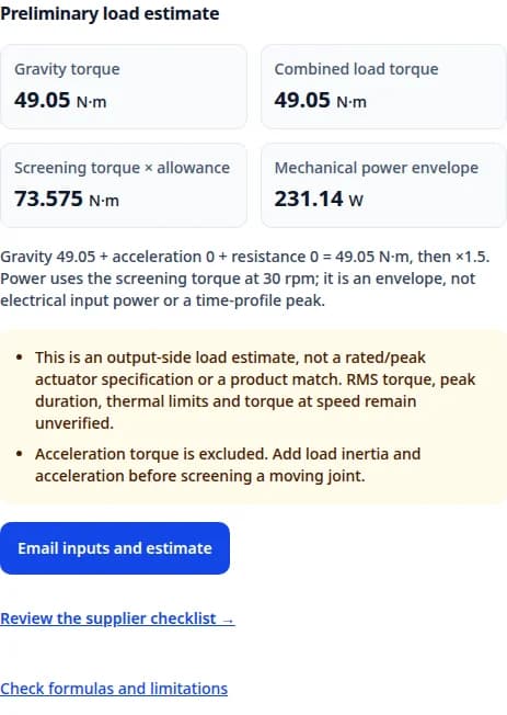
Inputs default to 10 kg, 0.5 m and 30 rpm, with zero acceleration, inertia and resistance. The editable 1.5 allowance is an illustrative engineering choice. Input limits are software bounds, not verified product operating ranges. Gearbox efficiency, motor rotor inertia, multi-axis coupling, contact forces and electrical losses are outside this calculation.
| Quantity | Available here | Needed for selection |
|---|---|---|
| Load torque / mechanical power | Calculated from entered values; no catalog check | A verified torque-speed-time trajectory |
| Continuous / RMS requirement | Unknown without cycle durations | RMS profile and thermal validation under intended cooling |
| Actuator peak torque / duration | Unknown; no universal multiplier or duration | Motor, gearbox and drive limits at speed and temperature |
| Electrical input / regeneration | Unknown; output power is not input power | Efficiency, current, bus voltage and braking-energy data |
| Exact model / price / lead time | Unknown; no verified catalog or quote connected | Supplier offer and documented acceptance criteria |
Three reproducible sizing examples
These are synthetic engineering examples, not tested robot or product performance. Use the matching buttons in the calculator. All use a 1.5 allowance; the equations above reproduce each result.
| Scenario | Inputs | Result | Next decision |
|---|---|---|---|
| Gravity hold | m=10 kg, L=0.5 m; J=0 kg·m², α=0 rad/s²; resistance=0 N·m, speed=0 rpm | Tload=49.05 N·m; Tscreen=73.575 N·m; P=0 W | Validate holding current, temperature and loss-of-power support. |
| Accelerating shoulder | m=10 kg, L=0.5 m; J=1 kg·m², α=2 rad/s²; resistance=1 N·m, speed=30 rpm | Tload=52.05 N·m; Tscreen=78.075 N·m; P=245.28 W | Check the actual cycle and peak duration; the summed envelope is not RMS. |
| Vertical yaw axis | m=5 kg, L=0 m; J=0.8 kg·m², α=3 rad/s²; resistance=0.4 N·m, speed=15 rpm | Tload=2.8 N·m; Tscreen=4.2 N·m; P=6.5973 W | Zero gravity moment does not remove acceleration torque. Verify inertia from CAD. |
Continuous duty and short torque peaks
At the same reference shaft, T_RMS = √(Σ(Ti² × Δti) / ΣΔti). Include holding, acceleration, deceleration and rest intervals. RMS is a thermal screening input; the complete speed history and manufacturer limits still matter. Duty-cycle timing is part of motor selection. [S6]
| Segment | Torque (N·m) | Duration (s) | T² × duration |
|---|---|---|---|
| Move | 40 | 2 | 3,200 |
| Hold | 20 | 6 | 2,400 |
| Unloaded rest | 0 | 2 | 0 |
For this invented cycle, RMS = √(5,600/10) = 23.66 N·m, while the load peak is 40 N·m. A 40 N·m peak rating alone cannot establish suitability. Confirm whether the real rest interval is unloaded; a suspended payload still needs holding torque or independent support.
Rated torque is conditional on rated speed/current and operating conditions. Use product-specific peak curves and timing rather than assuming a 2–4× peak ratio or a 1–3 second limit. [S1]
Gear ratio and inertia: name the reference side
With reduction ratio i = motor speed / output speed, load inertia referred to the motor is Jload/i². Conversely, rotor inertia referred to the output is Jmotor×i². A high ratio reduces the first quantity while increasing the second. [S2]
An inertia ratio is a design input, not a universal pass/fail threshold. Drive response, stiffness, feedback and the motion task affect workable values; historical 1:1–3:1 rules do not validate a modern mechanism by themselves. [S3]
Prepare your supplier sizing brief →Selection matrix: architecture and integration trade-offs
Use this qualitative shortlist to decide what to test. Frameless versus housed describes packaging; direct drive versus geared describes transmission. A frameless motor can be used inside a geared module.
| Option | Reason to investigate | Trade-off / evidence to request | Reference |
|---|---|---|---|
| Direct drive (i=1) | Avoid transmission backlash and reduction-stage losses | Motor must supply output torque directly; verify size, cooling and load bearings. | [S2] |
| Low-ratio / QDD | Investigate backdrivability and responsive physical interaction | Measure friction, force-estimation error and impact behavior; no universal sensor exemption or gear-ratio cutoff. | [S5] |
| Strain-wave geared | Compact reduction with zero-backlash designs available | Check torsional stiffness, accuracy, speed, efficiency and shock limits separately. | [S4] |
| Housed integrated module | Reduce separate mechanical and drive integration tasks | Confirm included bearings, brake, encoder, protocol and serviceability; packaging alone does not specify backlash. | Supplier-specific evidence required |
| Frameless motor kit | Control the mechanical envelope and thermal path | Budget for housing, bearings, feedback, alignment and validation; compare the whole installed assembly. | [S2] |
Misuse, cost and application risks
The actions below are engineering review recommendations for this workflow. They are not supplier performance guarantees or price benchmarks.
| Risk | Decision impact | Minimum mitigation / alternative |
|---|---|---|
| Using payload only | Link mass, geometry or acceleration can dominate the estimate. | Obtain CAD mass/inertia and a time profile; reduce reach or acceleration and recalculate. |
| Thermal assumptions | A catalog rating may not apply to the installed housing and ambient. | Request a derating curve and run a representative temperature-rise test; no universal 30% derating assumption. |
| Contact / impact mismatch | A gravity model misses traction, ground forces and collisions. | Use a traction or contact-dynamics model, measured loads and hardware limits. |
| Total installed cost | A motor-only quote omits drive, encoder, brake, bearings, tooling and commissioning. | Compare equal-scope installed quotes and prototype versus production costs; amounts and lead times are unknown until quoted. |
| Oversizing and energy | Extra moving mass can raise upstream-joint and supply requirements. | Iterate system mass and duty cycle; compare geometry or trajectory changes before adding torque. |
| Power loss / human interaction | A sizing allowance does not establish safe load holding or force limitation. | Specify the protective functions and load-support strategy separately, then validate at system level. |
Turn the estimate into a supplier sizing brief
Use “Email inputs and estimate” beside the result to transfer your assumptions. Attach the missing information below. A candidate stays unverified until the required evidence is supplied.
| Provide | Ask the supplier to return | Acceptance decision |
|---|---|---|
| CAD mass, gravity arms and inertia; worst poses | Output torque-speed envelope for the proposed configuration | Compare all modeled load points at the same reference shaft. |
| Torque/speed versus time and repeat interval | Continuous capability, peak duration and protection behavior | Confirm both the cycle and short excursions, including holding. |
| Ambient, enclosure and cooling path | Applicable thermal conditions and derating data | Recheck the installed configuration, not just the catalog setup. |
| Bus voltage and braking/deceleration profile | Drive current limits, efficiency data and regeneration handling | Verify electrical demand and energy absorption separately. |
| Flange, bearing loads, brake, encoder and protocol | Drawings, load limits, interface and commissioning documents | Resolve mechanical and control compatibility before ordering. |
| Quantity, schedule and validation plan | Itemized quote, lead time and agreed test evidence | Keep commercial estimates separate from engineering acceptance. |
Request a sizing review
Send your load profile and required interfaces. State unknowns explicitly so the review can identify the next measurement or calculation.
Inquiry Email
Send target torque/speed, protocol, quantity, and delivery location.
Methodology and traceable sources
Published by Robotic Joint Module on . Editorial review covers the formulas, source scope and software behavior. Next review is due by 2027-03-27, or sooner if a cited source or calculation changes.
Reviewed on . Manufacturer references support definitions and design considerations; the research paper supports a specific actuator approach. Neither supplies a verified catalog match for the inputs above. Worked examples are our calculations, not measurements. Prices, availability and application-specific ratings remain unknown.
- [S1] Kollmorgen — Motor Data Legend
Published 2013-11-07. Definitions of rated and standstill torque, current and thermal conditions; no universal peak-duration rule.
- [S2] Kollmorgen — Demystifying the Use of Frameless Motors in Robotics
Published 2019-02-14. Load profiling, thermal/mechanical integration and load inertia reflected through gearing; not a catalog match for this tool.
- [S3] Kollmorgen — Energy Management of a Servomotor: Effects of Inertia Ratio (PDF)
2015 white paper, pp. 2–4. Explains why historical inertia-ratio rules are application dependent.
- [S4] Harmonic Drive — Strain Wave Gear Principle
Undated manufacturer explanation. Supports zero-backlash gearing; does not imply zero elastic deflection or universal impact capacity.
- [S5] MIT — Proprioceptive Actuator Design in the MIT Cheetah (PDF)
2017 research paper, author proof; DOI 10.1109/TRO.2016.2640183. Low-ratio actuation and force control in a specific robot, not proof for all QDD modules.
- [S6] Kollmorgen — What You Should Know About Frameless Motors
Published 2021-07-12. Duty-cycle timing, RMS torque, peak conditions and installation affect selection.
Sizing and selection questions
Using the calculator
Can payload alone size an actuator?
No. The same mass creates different gravity moments at different lever arms. Include downstream links and tooling, then obtain inertia and a motion profile.
What does a zero gravity moment arm mean?
It means gravity produces no torque about this axis, as for an ideal vertical yaw axis. Acceleration, friction and external forces may still require torque.
Why does the calculator not recommend a model?
No verified product catalog or torque-speed curves are connected. It produces a requirements brief; a model recommendation needs continuous, peak, thermal and interface evidence.
Can I use this for an AGV or a walking robot?
Use the application selector to get an alternative checklist. Traction and contact forces need a different model; substituting wheel radius for gravity moment arm is not valid.
Interpreting the result
Is screening torque the continuous rating I should buy?
No. It is a load envelope multiplied by your allowance. Continuous sizing also needs a time history, RMS torque, cooling conditions and a speed-dependent continuous curve.
How long can peak torque last?
Use the selected motor, drive and gearbox limits, including current, initial temperature and repetition interval. There is no universal 1–3 second duration. See S1 and S6.
Does zero output power mean zero heating?
No. At zero rpm, torque times speed is zero, while a motor holding a gravity load may draw current and dissipate heat. Check holding duty and brake requirements.
Is the multiplier a safety certification?
No. The default 1.5 is an editable example allowance. It cannot certify a collaborative robot, exoskeleton, brake or protective function.
Choosing hardware
Does a higher gear ratio increase reflected inertia?
Load inertia referred to the motor falls as Jload/i². Motor rotor inertia referred to the output rises as Jmotor×i². State the reference side before comparing. See S2.
Do strain-wave gears necessarily have backlash?
No. Harmonic Drive specifies zero-backlash strain-wave gearing. Torsional compliance and transmission accuracy are separate properties to check. See S4.
Can a low-ratio drive always replace a torque sensor?
No. Current-based force estimation depends on the mechanical design, friction and control model. MIT demonstrates one design; measurement and safety needs must be assessed for your robot. See S5.
What should I send with a sizing inquiry?
Send the inputs and estimate, CAD mass/inertia, a torque-speed-time profile, ambient temperature, cooling, bus voltage, interface, quantity and acceptance criteria. Mark any missing item as unknown.