
Actuator evidence review
Actuator Module for Robots: Reliability and Safety
Build supplier questions from your operating conditions, then plan validation.
Request a supplier evidence reviewReliability & safety evidence checker
Build a review checklist. MTBF and safety performance remain unverified.
Four decisions before selecting a module
Ask for evidence before a lifetime claim
Operating labels cannot establish a numerical MTBF. Require relevant test data, assumptions and uncertainty.
Define the safety function before the architecture
Record the hazard and required response before comparing component specifications. A selected target is not achieved performance.
Separate torque removal from load retention
STO can leave a coasting or gravity-driven axis. Review how the application stops and retains its load.
Check sector and integration scope
Industrial robot guidance does not automatically cover medical, aerospace, public service or mobile-platform hazards.
How the checker works — and where it stops
The checklist rules are editorial engineering prompts. They select review topics, not failure probabilities or mandatory architectures. Harsh exposure adds a qualification question; a heavy payload adds a load review; non-industrial scope adds a specialist review. Every result retains unresolved evidence.
| Input or claim | Known here | Still required |
|---|---|---|
| Operating categories | User selections only | Measured torque-speed-time profile, reach, inertia, cooling and exposure |
| Reliability / MTBF | Unknown | Relevant exposure, failures, model, uncertainty and configuration |
| Safety performance | User-stated target, if any | Complete safety-function design and validation evidence |
| Braking / retention | Load-support selection only | Rated load, engagement behavior, safe-state and power-loss tests |
Read reliability metrics without mixing their purpose
For a constant repair-rate model, NIST describes estimation from total exposure and observed failures. Zero failures do not prove infinite lifetime: a one-sided lower confidence bound needs a stated confidence level. See NIST: constant repair rate model. This tool does not apply that model.
| Claim on a datasheet | Ask the supplier | Decision limit |
|---|---|---|
| MTBF | Which model, exposure, failures, operating conditions and confidence interval? | Not a guaranteed service life or a safety approval |
| Wear life / maintenance interval | Which load spectrum, lubrication, environment and end-of-life criterion? | Do not replace a maintenance limit with MTBF |
| MTTFd / B10d / PFHd | Which safety function, failure classification, calculation method and operating assumptions? | Do not substitute general MTBF for dangerous-failure data |
| PL / SIL claim | Which exact function, configuration, standard, certificate scope and integration restrictions? | A component label does not verify the whole robot |
Control-system methodology scope: ISO 13849-1:2023. The table is a procurement checklist; detailed calculations require the applicable standard and component documentation.
Failure modes to investigate
Use these engineering hypotheses to start an application FMEA. No universal temperature, vibration, diagnostic-coverage or brake-life threshold is assumed.
| Failure mode | Evidence to collect | Candidate mitigation to validate |
|---|---|---|
| Thermal overload | Torque-speed duty trace, ambient and measured winding / housing temperatures | Cooling or torque derating within supplier limits; verify the final motion cycle |
| Bearing / reducer wear | Load spectrum, shock events, lubricant and wear inspection records | Reduce loads, revise support or select a rated module; confirm maintenance intervals |
| Feedback loss / drift | Fault detection behavior, wiring layout and signal-integrity test records | Validate diagnostics, routing and defined fault response; redundancy alone is insufficient |
| Brake or retention failure | Rated holding load, stopping-energy limits, engagement time and wear criteria | Specify retention independently of STO; validate safe stop and power-loss behavior |
| Ingress / connector damage | Actual washdown, dust and vibration profile plus qualification reports | Use documented environmental protection and qualified connections |
Scope and limitations: ISO 10218-1:2025; drive-specific stopping example: Schneider Electric: requirements for STO.
Standards are a scope check, not a certificate
| Reference | Review purpose | Boundary |
|---|---|---|
| ISO 13849-1:2023 | Design and integration of safety-related control systems | A performance target must be supported by the complete design and evidence |
| ISO 10218-1:2025 | Industrial robot safety | Medical, aerospace and public service applications are outside this scope |
| ISO 10218-2:2025 | Industrial robot applications and cells | Robot integration evidence is needed; mobile-platform hazards are not covered |
| ISO/TS 15066:2016 | Collaborative industrial robot guidance | Published specification under revision; do not transfer a single contact number to every scenario |
Sources: ISO 13849-1:2023; ISO 10218-1:2025; ISO 10218-2:2025; ISO/TS 15066:2016. Public summaries verify scope only. This page does not determine jurisdictional compliance or substitute for full standards.
Compare the cost and risk of the validation plan
| Risk or choice | Consequence to investigate | Practical next step or alternative |
|---|---|---|
| Misuse: treating a score as approval | Unexamined stopping, retention or contact hazards | Keep unknowns explicit; validate each defined safety function |
| Cost: adding safety channels | Hardware, software integration and recurring validation effort | Ask for itemized module, integration and test costs; choose architecture from the risk assessment |
| Scenario mismatch: collaborative label | Tooling or trapping hazards remain in the complete application | Compare contact-limited operation with safeguarding or separation measures through an application assessment |
| Environment mismatch | Available qualification may not match washdown or vibration | Compare a documented protective enclosure, a qualified module or a revised operating profile |
These comparisons are editorial planning advice, not measured product comparisons. Application context: ISO 10218-2:2025.
Reproduce the evidence checklist
Select Collaborative industrial robot, Continuous operation, Dust / washdown / vibration, PL e specified, Above 20 kg, and Suspended or externally driven. Build the checklist to reproduce the seven review topics below. The stated target is recorded, not verified.
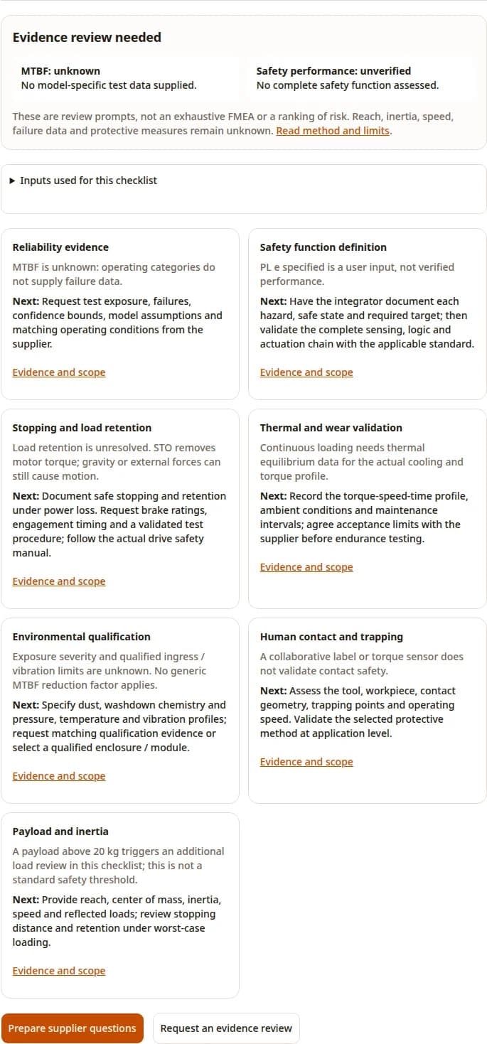
Three worked planning scenarios
Illustrative assumptions and checklist outcomes only; these are not field test results.
Factory pick-and-place
Assumptions: Industrial, intermittent, factory floor, 5–20 kg, load support unknown.
Process: Build the checklist, collect cycle and load data, and resolve stopping / retention.
Outcome: Evidence review needed; lifetime and achieved safety performance remain unknown.
Washdown collaborative cell
Assumptions: Collaborative industrial robot, continuous duty, harsh exposure, above 20 kg.
Process: Review qualification, contact geometry and inertia in addition to the baseline evidence.
Outcome: The checklist adds environment, contact and load questions. No contact limit or MTBF penalty is assigned.
Medical positioning axis
Assumptions: Medical use, controlled space, mostly standby, PL e stated by the user.
Process: Start a sector-specific standards review and request configuration-specific evidence.
Outcome: Specialist scope review needed. A selected PL e target does not establish suitability.
Prepare a supplier evidence request
Send the following pack for the exact module and firmware revision. If evidence is unavailable, record the gap and agree a test plan or compare a qualified alternative. No supplier report availability is assumed.
- Configuration: module, drive, encoder, brake, firmware, mounting and cooling.
- Mission profile: torque, speed, cycle timing, payload inertia, reach, environment and expected service period.
- Reliability evidence: test population, exposure, failures, exclusions, maintenance, uncertainty and applicability to this profile.
- Safety evidence: defined functions, manuals, certificate scope, integration restrictions and fault-response records.
- Validation agreement: acceptance criteria, responsible integrator, test method, review date and change-control process.
Inquiry Email
Send target torque/speed, protocol, quantity, and delivery location.
Evidence register and review limits
Published and reviewed by Robotic Joint Module on . The references support methods and scope. They do not establish a reliability figure or certification for products sold on this site. Checklist routing, test suggestions and scenarios are editorial inferences; supplier-specific evidence remains unknown. Review is due by 26 March 2027, or sooner if a cited standard or source changes. Send corrections through our contact page.
NIST: constant repair rate model
Statistical estimation from exposure and failures, with model assumptions and confidence bounds. No product reliability data.
ISO 13849-1:2023
Public scope: design and integration of safety-related control systems. The full standard and application evidence are needed for assessment.
ISO 10218-1:2025
Industrial robot scope and exclusions; not evidence of certification for any module.
ISO 10218-2:2025
Industrial applications and cells. Medical, public service and mobile-platform hazards require separate scope review.
Schneider Electric: requirements for STO
Drive-manufacturer example of coasting, external loads and brake limitations. Use the safety manual for the actual selected drive.
ISO/TS 15066:2016
Collaborative industrial systems; public catalogue lists the specification as published and to be revised. No universal contact limit is inferred here.
Frequently asked questions
Using the checker
Does this tool calculate MTBF?
No. It routes evidence questions from operating categories. It has no measured exposure, failure counts or validated lifetime model. See the method and supplier checklist.
Does selecting PL e or SIL 3 verify the design?
No. The selection records your stated target. It does not derive a required target, verify achieved performance or establish equivalence between standards.
Why is there no green pass score?
No model-specific test or safety-function evidence is submitted. A numerical pass score would imply confidence the checker cannot support.
What if my conditions are unknown?
Use the explicit unknown options for the target and load support. For other fields, gather the operating profile before using the result; the supplier checklist remains available without the tool.
Interpreting the evidence
Is MTBF the expected replacement interval?
It is a model-based reliability metric, not a guaranteed wear-out life. Request the applicable maintenance schedule and wear evidence separately. See the NIST source and metric table.
Does STO hold a vertical load?
STO alone does not establish load retention. Gravity and external forces can still move the axis. Check the actual drive and brake documentation and validate the stopping sequence.
Does a torque sensor make a robot collaborative-safe?
A sensor alone does not validate the application. Include the tool, workpiece, contact geometry, trapping hazards and chosen protective method in the review.
Can a component certificate cover the entire robot?
Only its defined scope and conditions are supported. Record the exact model, firmware, safety functions, interfaces and integration restrictions, then assess the complete application.
Planning a validation project
Can I use the industrial standards for a medical robot?
Do not assume coverage. The cited industrial robot scope excludes medical applications. Start with a sector-specific standards review.
Does payload below 5 kg imply low risk?
No. These bands only organize questions. Speed, reach, inertia, contact geometry, tooling and exposure can matter at any payload.
What should a supplier provide first?
Request the exact configuration, safety manual and certificate scope, reliability test conditions and results, torque-speed limits, load limits and brake specifications. Availability must be confirmed.
What if the supplier has no applicable evidence?
Keep the claim unknown. Agree a bounded validation plan with acceptance criteria or compare a module with relevant documented qualification. Do not substitute a generic lifetime figure.