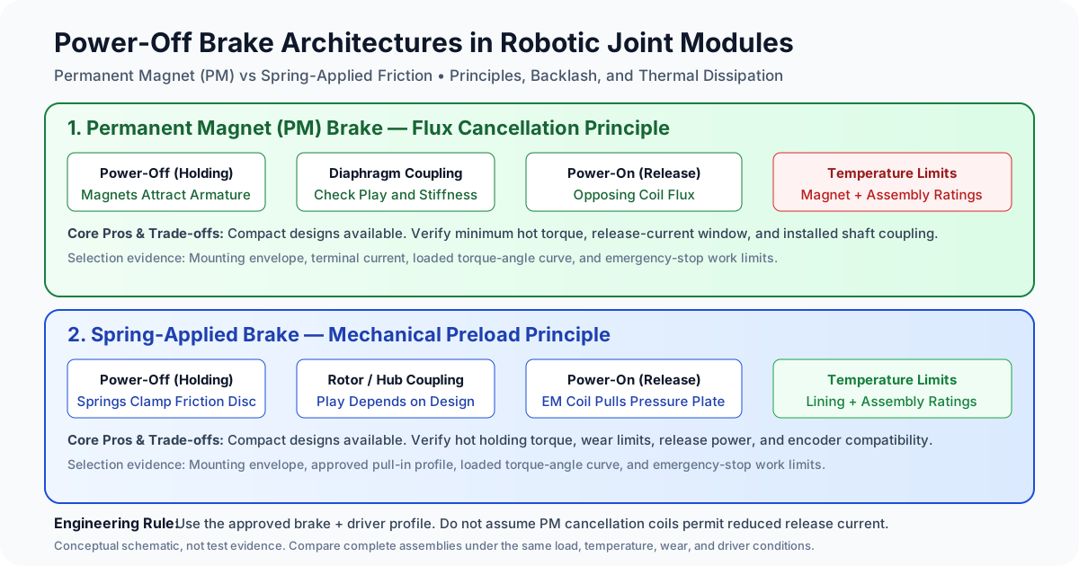
Permanent Magnet vs Spring-Applied Power-Off Brakes in Robotic Joint Modules: Holding Torque Density, Thermal Dissipation, Engagement Latency, and Fail-Safe Sourcing Guide
Compare permanent magnet vs spring-applied robot joint brakes for torque, heat, backlash and engagement time. Use the RFQ checklist to shortlist suppliers.
Permanent magnet vs spring-applied power-off brakes: shortlist by the installed joint's minimum holding torque, permitted movement after power loss, available space, release-power budget, and documented emergency-stop duty. Permanent magnet (PM) diaphragm designs can be attractive where compact packaging and a backlash-free coupling matter. Spring-applied designs offer several friction-disc and hub arrangements, including compact versions for robotics. Neither principle alone establishes the best torque density, temperature limit, stopping time, or safety capability.
This guide is for robot hardware architects, mechatronics teams, and OEM procurement managers comparing holding brakes for robotic joint modules. It addresses static holding, release-coil heating, engagement latency, and supplier evidence rather than recommending a brake from its architecture label.
Published and reviewed: November 6, 2026. Scope: Global OEM sourcing; English-language engineering guidance. The comparison uses manufacturer descriptions and explicitly labelled analytical examples. It contains no original brake test results or customer performance claims. Industrial robot standards do not automatically cover humanoids, surgical systems, or AMR applications; determine the applicable requirements for the complete machine and destination market.
If you are defining an actuator BOM, explore our robotic joint actuator catalog or send your axis requirements for an application engineering RFQ review.
1. Executive Summary & Sourcing Trade-Off Matrix
Both architectures can be configured as normally applied, electrically released holding brakes. Loss of release power causes an engagement sequence; it does not create full rated torque instantaneously. Safe Torque Off (STO) removes motor torque production but does not by itself apply or prove a mechanical brake. Gravity-loaded axes need a coordinated control and mechanical protection strategy.
Use the matrix to decide what to ask each supplier. Entries describe selection questions, not guaranteed ranges shared by every product in a category.
| Architectural & Procurement Metric | Permanent Magnet Power-Off Brake | Spring-Applied Electromagnetic Brake | Evidence Needed for Selection |
|---|---|---|---|
| Operating principle | Permanent magnet attraction supplies clamping force; an opposing coil field permits release. | Mechanical springs supply clamping force; an energized coil pulls the armature against spring force. | Drawing, wiring polarity, and defined powered/unpowered states. |
| Holding torque density | Compact diaphragm designs are available. | Compact servo and hollow-shaft designs are also available. | Minimum rated torque divided by the same installed-volume definition. |
| Rotational backlash | A diaphragm coupling can avoid clearance play while retaining elastic compliance. | Play depends on the rotor and hub connection; do not assign one spline-play range to every design. | Loaded reversal test, mounting interface, and torsional stiffness. |
| Release and engagement time | Depends on current, temperature, gap, and driver behavior. | Depends on spring force, magnetic circuit, gap, and driver behavior. | Worst-case time to the specified torque with the supplied driver. |
| Continuous release heat | Cancellation current must remain in the approved release window. | Some models permit a reduced current after pull-in. | Approved drive profile and measured hot coil power. |
| Thermal limit | Magnet properties, winding, adhesive, and friction interfaces all matter. | Winding, springs, lining, and insulation all matter. | Complete brake temperature rating and hot torque evidence. |
| Emergency dynamic stops | Allowed only within the particular model's documented energy and wear limits. | Allowed only within the particular model's documented energy and wear limits. | Single-stop energy, speed, cumulative work, and inspection limits. |
| Wear and contamination | Friction contact can still generate debris during slipping or abnormal operation. | Friction contact can generate debris during slipping or abnormal operation. | Wear records, enclosure design, and encoder compatibility. |
| Driver interface | Correct polarity and cancellation current are critical. | Coil polarity may be constrained by built-in electronics or suppression. | Terminal voltage/current limits and approved suppression network. |
| Procurement cost | Quote the complete brake, driver, mounting, and qualification package. | Use the same scope and quantities for comparison. | Dated quotations, tooling, lead time, and change-control terms. |
Manufacturer context supports comparing actual products: Kendrion's PM overview describes compact, backlash-free coupling designs and emergency-stop capability. Its spring-applied overview includes servo and extra-flat hollow-shaft families. Those portfolios do not establish a universal architecture ranking.
2. Electromechanical Principles & Magnetic Circuits
2.1 The Flux Cancellation Mechanism in Permanent Magnet Brakes
In a PM holding brake, permanent magnets attract an armature toward a stationary pole face while the release coil is unpowered. Energizing the coil in the specified direction opposes the magnet field, allowing a spring element to separate the friction surfaces. The exact release current depends on the magnetic circuit, temperature, air gap, and tolerances.
An idealized relationship is F = B² × A / (2 × μ₀) and T = μ × F × r, where B is working-gap flux density, A is active pole area, μ₀ is air permeability, μ is friction coefficient, and r is effective friction radius. These explain why field and surface condition matter. Leakage, saturation, contact geometry, and friction variability prevent using this simple model as a catalogue torque guarantee.
The release state is a bounded operating window. Incorrect polarity can reinforce rather than cancel attraction; excessive cancellation current can also restore attraction as net field magnitude rises. Neither the force increase nor the failure threshold is a fixed multiplier. Request the allowed current range at cold and hot conditions, and check terminal measurements with the actual harness.
2.2 Mechanical Preload Mechanics in Spring-Applied Brakes
In a spring-applied design, springs push an armature against a friction rotor when the coil is unpowered. Coil attraction retracts the armature to release the rotor. A sliding hub is one possible arrangement, not a definition of the entire category.
For a simplified two-interface disc, holding torque is T = 2 × μ × F × r, with F the clamping force at each interface and r the effective friction radius. Different interface counts or pressure distributions change the relationship. Ask the supplier for minimum torque after its specified run-in procedure and at the required environment rather than selecting a friction coefficient from a generic range.
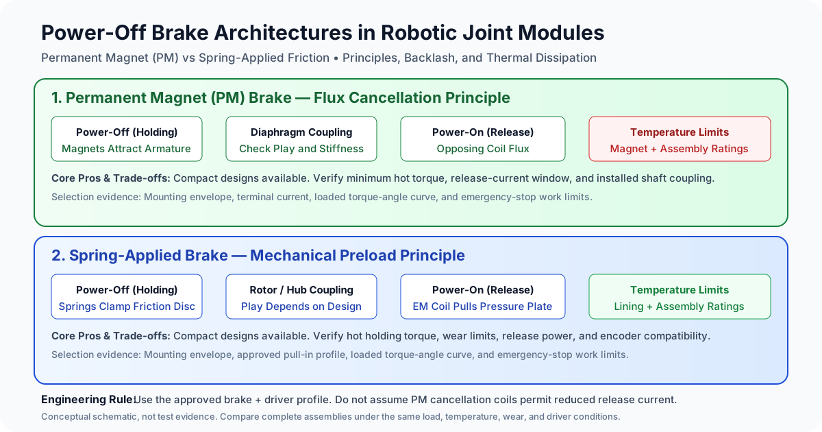
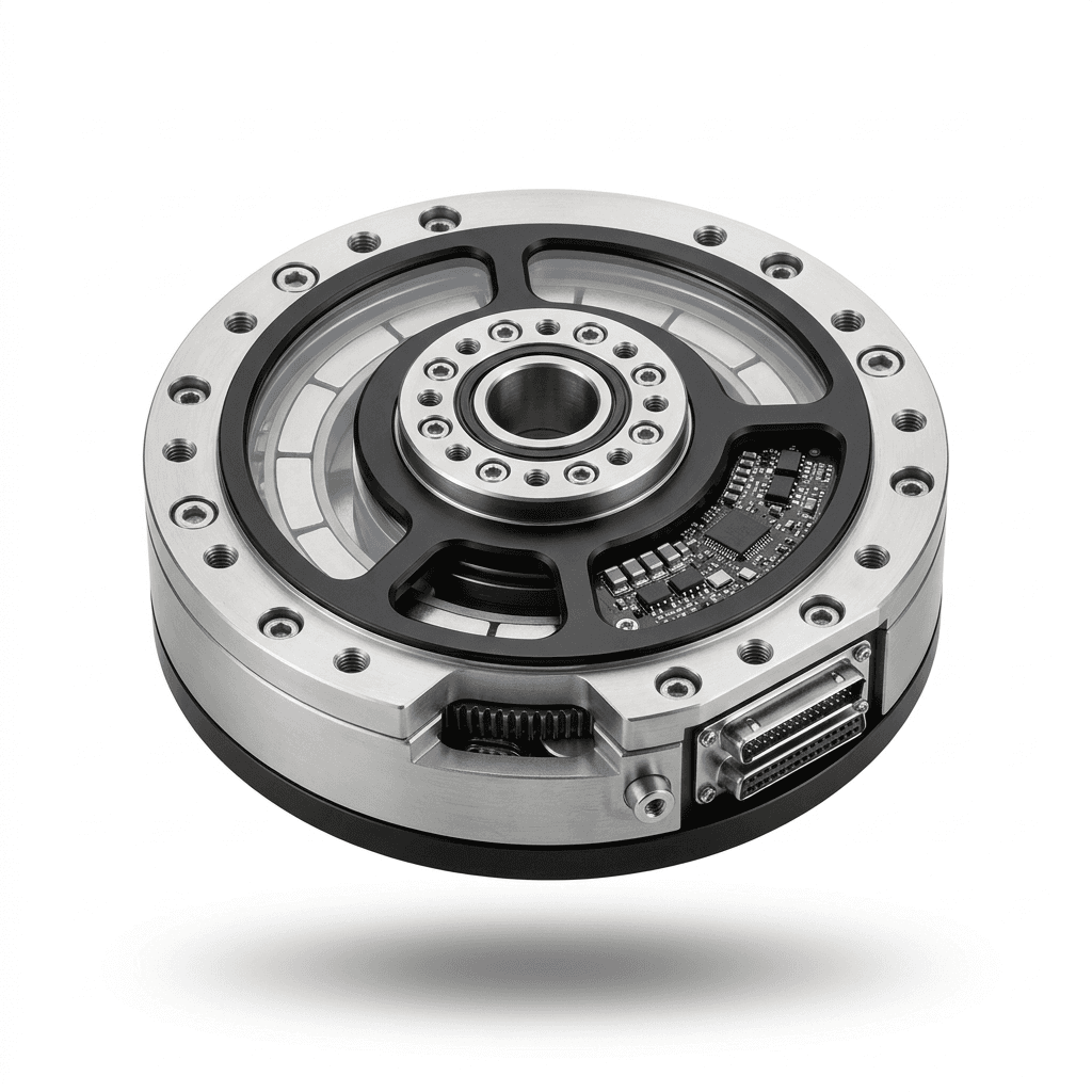
Architecture illustration, not a dimensional drawing or measured performance comparison. Coupling play, temperature ratings, and approved drive profiles remain model-specific.
2.3 Backlash, Compliance, and Brake Shaft Location
Separate clearance backlash from elastic twist. A coupling advertised as backlash-free still deflects under load, and reducers, bearings, flanges, and housings add movement. Obtain a torque-versus-angle curve under positive and negative load rather than accepting “zero backlash” as a claim of zero tool displacement.
The following is a hypothetical geometric example, not measured brake performance:
Assume angular clearance at the joint output = 0.8 degrees
Downstream reach = 850 mm
Approximate tip movement = 850 × (0.8 × pi / 180) = 11.87 mm
If the same clearance is on the motor side of a reducer with ratio N, its ideal output contribution is divided by N. Reducer compliance and lost motion need separate treatment. The example cannot predict gravity drop, because closing delay and dynamic stopping add further movement. Always identify which shaft each quoted angle refers to.
For torque density, use the same basis: for a cylindrical envelope, V = pi × D² × L / 4, with D and L in consistent units. State whether the bore, hub, flange, and driver space are included. Compare minimum hot holding torque per installed volume and per mass; a smaller bare brake can require a larger installed assembly.
3. Thermal Dynamics: Coil Power & Joint Heat Dissipation
3.1 Release-Coil Power and Approved Economizing
Brake-coil heating normally occurs while the brake is electrically released and the robot can move. Unpowered static holding requires no release-coil power, although the surrounding motor and electronics may still heat the brake.
A hypothetical 24 V coil with resistance 48 Ω at the stated reference temperature draws I = V/R = 0.5 A and dissipates P = V²/R = 12 W. This is electrical arithmetic, not a prediction for a particular brake. Joint temperature rise additionally depends on conduction paths, mounting contact, convection, motor losses, and operating duty. Housing diameter alone cannot determine that rise.
Some spring-applied brakes permit a pull-in stage followed by reduced current. Use the supplier's profile, including maximum pulse voltage and duration, minimum release current, and fault behavior. Do not apply this economizing pattern to a PM cancellation brake without explicit manufacturer approval. Reducing PM current below its release window may reapply the brake while motion is commanded.
For an illustrative approved current reduction from 0.5 A to 0.25 A at an unchanged 48 Ω, copper loss changes from 12 W to I²R = 3 W. This 75% reduction is conditional on the assumed currents and resistance; it is not an available saving for every product. With PWM, copper heating follows I_rms² × R. Duty cycle alone does not establish RMS current, because inductance, switching frequency, and recirculation topology affect ripple.
Measure at the brake terminals after thermal stabilization. Record coil temperature or resistance, supply extremes, PWM frequency, adjacent motor operating point, and release clearance. Include the hottest sustained duty and repeated starts. Verify that a low-power setting still releases reliably rather than trading heat for undetected friction drag.
3.2 Magnet Temperature Limits Are Not Curie Temperature
PM holding force is affected by reversible magnet-property changes and, under unsuitable temperature and opposing-field conditions, irreversible demagnetization. A magnet's recommended operating temperature is different from its Curie temperature. Neither a generic grade suffix nor a Curie value establishes the safe operating temperature of an assembled brake.
For PM candidates, request the magnet material, demagnetization margin at the actual operating point, and minimum holding torque across the complete brake's rated temperature range. SmCo may be considered when its material properties suit the design, but it does not make windings, adhesives, bearings, or friction surfaces immune to heat.
For spring-applied candidates, request equivalent hot and cold torque, release-current, and wear evidence. Avoid assuming that the absence of permanent magnets creates unlimited thermal resilience: lining behavior, spring relaxation, insulation, and dimensional changes can still set limits. Use the lowest applicable component or assembly rating and confirm it through the agreed qualification procedure.
4. Engagement Latency, Coil De-energization & Drop Dynamics
4.1 Coil Decay and Time to Useful Torque
Specify the measured event endpoints. The delay from a controller command to electrical cutoff, current decay, armature travel, and torque buildup are different intervals. A supplier's contact-closing time may end before the torque needed to hold your load has developed. Test the complete driver, harness, suppression circuit, and brake assembly.
A simple resistance-dominated RL decay has time constant τ = L/R. A diode recirculation path can slow field collapse; a higher-voltage clamp can shorten it but increases electrical stress. A Zener or TVS clamp does not behave as a constant extra resistance, so one exponential formula cannot predict every suppression circuit. Specify coil insulation, switch and clamp ratings, and allowable transients with the supplier. Avoid choosing a clamp voltage from a generic timing example.
Record current and shaft motion together and establish the time at which the required resisting torque is available. Repeat at supply extremes, hot and cold conditions, and the maximum permitted wear gap. Polarity, residual magnetism, friction condition, and the actual release profile can affect results. There is no architecture-wide guarantee of a particular millisecond closing time.
4.2 Gravity Drop and Reducer Shock Load Calculations
For a simplified rigid axis starting at rest, constant gravity torque Tg and inertia J give angular acceleration α = Tg/J. If useful brake torque is absent for delay td, then ω_contact = α × td and θ_delay = 0.5 × α × td².
If constant dynamic brake torque Tb then exceeds Tg, additional slip angle is θ_slip = J × ω_contact² / [2 × (Tb − Tg)]. Total predicted angle is θ_delay + θ_slip. All torque, inertia, speed, and angle values must be referred to the same shaft. Include nonzero initial speed for an axis already moving. The model excludes torque-rise shape, flexible transmission dynamics, and impacts.
A reproducible hypothetical output-shaft example uses Tg = 20 N·m, J = 2 kg·m², td = 0.04 s, and Tb = 60 N·m. It gives α = 10 rad/s², contact speed 0.4 rad/s, delay movement 0.008 rad, and slip movement 0.004 rad. Total movement is 0.012 rad, approximately 0.69 degrees, before adding clearance or compliance. Brake friction work during slip is Tb × θ_slip = 0.24 J, including gravity work during that interval.
These are assumed inputs, not a tested stop or a recommended rating. When Tb is no greater than Tg, this model cannot arrest the load. A motor-side brake needs reflected inertia and torque plus transmission efficiency and backdriving analysis; do not combine output gravity torque with motor-side brake torque.
Faster engagement can reduce acceleration time but does not by itself prove acceptable gearbox shock. Coordinate normal servo deceleration with brake application, and assess uncontrolled power-loss stopping separately. Validate load movement, peak transmission torque, emergency energy, and post-stop holding in the physical assembly.
5. Wear Debris Contamination & Sealed Hollow-Shaft Integration
5.1 Friction Dust and Encoder Compatibility
Both brake families use friction to hold a shaft and can generate particles when surfaces slide. A brake engaged at rest has a different wear mechanism from one absorbing kinetic energy. Do not infer zero particle generation from a PM design or cleanroom suitability from a product photograph.
For either architecture, request the lining/contact materials, permitted lubrication state, wear-gap limits, and particle-control provisions. Review adjacent optical encoder surfaces and magnetic rings for contamination sensitivity. Also check lubricant migration from the reducer: sealing external dust out does not isolate an internal source of grease or debris.
5.2 Isolation, Seals, and Hollow-Bore Routing
Consider a separated brake chamber, labyrinth, or compatible seal when contamination analysis requires it. A labyrinth reduces transport but does not guarantee particle-tight isolation. Contact seals add drag, wear, and heat, so include them in release-torque and thermal testing.
Protect through-routed cables from rotating hubs, sharp edges, and lubricant. Confirm the required bore remains usable after connectors, strain relief, and any sleeve are installed. Cleanroom and medical applications require assembly-level particle, cleaning, and material compatibility evidence. Do not assume the complete actuator can tolerate sterilization because one magnet material has a high temperature rating.
6. Joint-by-Joint Allocation Decision Framework
Start with posture-dependent load and the consequence of loss of hold. A small wrist can have a strict tool-movement limit, while a proximal axis may demand greater emergency energy absorption. Humanoid balance may require more than locking individual joints. Define the fault response of the complete machine before choosing the brake family.
| Joint or Application | Primary Question | Selection Evidence |
|---|---|---|
| Humanoid hip or knee | What happens to balance after power loss? | Whole-body fault response, contact speed, joint load, and holding evidence. |
| Humanoid arm or neck | How much mass and movement are acceptable? | Installed mass, coupling curve, and worst-case posture torque. |
| Cobot base or shoulder | Which loads reach the brake shaft? | Axis geometry, transmission location, reflected inertia, and emergency duty. |
| Cobot wrist | How does angular movement affect the tool? | Tool reach, output displacement budget, and torsional stiffness. |
| Surgical manipulator | What cleaning and risk controls apply? | Device-specific requirements, validated materials, and assembly testing. |
| AMR traction or steering | Is this parking duty or a moving stop? | Grade holding, stopping energy, manual recovery, and service procedure. |
Neither PM nor spring-applied should be mandated solely by axis number. Compare candidates using the same temperature, speed, envelope, and driver assumptions. A suitable brake may change when the gearbox ratio, tool length, or required emergency-stop frequency changes.
Before requesting samples, use the application engineering contact page to share a shaft-location sketch and the comparison conditions. This makes supplier responses easier to compare and exposes missing requirements before hardware qualification.
7. Sourcing & RFQ Engineering Checklist (Buyer Validation Worksheet)
Use this checklist to define evidence and acceptance criteria with the supplier. Numerical thresholds must come from the application risk assessment, applicable requirements, and the selected component's documentation. “Certified” should identify an issuer, scope, document, and revision; it must not be a substitute for measured values.
Gate 1: Holding Torque and Shaft Reference
- Identify the brake shaft, gear ratio, backdriving assumptions, worst posture, payload, and external loads.
- Specify minimum holding torque at temperature and wear limits, with a justified application margin.
- Record the torque-test method, run-in state, sample identification, and acceptance authority.
Gate 2: Electrical Drive and Heat
- Obtain permitted polarity, release current range, supply tolerance, and pulse limits.
- Confirm any economizing profile is approved for this exact brake and driver combination.
- Measure hot RMS current, coil power, local temperature, residual drag, and release reliability.
Gate 3: Response Time and Power-Loss Behavior
- Define timing endpoints through the required resisting torque, including control and driver delays.
- Record the actual suppression circuit and test current decay with the production harness.
- Validate load movement and the failure response at worst speed, temperature, voltage, and wear.
Gate 4: Backlash and Torsional Stiffness
- Obtain loaded reversal curves at the stated shaft and load level for both architectures.
- Allocate clearance and elastic deflection across the brake, reducer, bearings, and housing.
- Confirm tool displacement stays within the application's movement budget after engagement.
Gate 5: Contamination and Integration
- Review friction debris, lubricant migration, encoder compatibility, and any required isolation.
- Check mounting runout, axial movement, bore routing, seal drag, and service access.
- Obtain cleaning and environmental evidence for the complete assembly where required.
Gate 6: Emergency Duty and Maintenance
- Obtain permitted single-stop work, speed, cumulative work, event count, and cooling interval.
- Define post-stop inspection, torque checks, wear limits, replacement criteria, and warranty exclusions.
- Confirm machine-level safety claims separately from the component's normally applied behavior.
Gate 7: Traceability and Commercial Scope
- Agree insulation and dielectric test requirements using the relevant component and machine documentation.
- Obtain drawing revisions, material/change notification, lot traceability, and inspection deliverables.
- Compare brake, driver, tooling, qualification, maintenance, lead time, and volume pricing together.
8. Frequently Asked Questions (FAQ)
Can a power-off holding brake slow down a robot during normal trajectories?
Use the servo and the designed energy-management system for normal motion control. A holding brake can absorb motion only where its model-specific dynamic duty permits it. Some brakes are designed for repeated braking work, while others allow limited emergency stops. “Power-off” alone establishes neither service-brake capability nor a lifetime stop count.
Why might a PM brake fail to release at nominal supply voltage?
Check wiring polarity, terminal voltage under load, actual coil current, temperature, air gap, and mounting condition against the supplier's release window. Also check for mechanical interference or contaminated friction surfaces. Nominal voltage measured at the power supply does not prove correct current at the brake. Remove the axis from operation and support the load before troubleshooting.
What is the maximum acceptable backlash for a collaborative robot brake?
There is no universal brake-angle limit for all cobots. Derive the limit from permissible output or tool movement, reach, shaft location, reducer behavior, and the consequence of unexpected motion. Ask for clearance and stiffness separately. A backlash-free coupling can reduce clearance motion but cannot eliminate elastic deflection or engagement delay.
How does PWM affect nearby encoder lines?
Switching current can couple into encoder wiring. Review current-loop area, harness separation, shielding, grounding, and suppression with the drive and encoder suppliers. Verify signal integrity and fault behavior on the assembled joint during switching and fault transients. A chosen switching frequency does not by itself prove electromagnetic compatibility.
Is emergency dynamic wear covered by a standard warranty?
Coverage is contractual. Request written limits for speed, energy per event, cumulative work, event count, contamination, and maintenance. Record which stop events require inspection or replacement. Do not translate a claimed static switching life into an equivalent number of moving emergency stops.
Does a normally applied brake make the joint fail-safe?
Normally applied describes a default operating principle. Safety depends on sufficient torque, engagement behavior, wear, contamination, wiring and control faults, diagnostic coverage, and machine integration. Require evidence for any claimed safety function and its exact scope. A brake label or a dual-channel output alone does not prove the complete axis is safe.
9. Sources, Standards & Evidence Boundaries
- Kendrion — Permanent Magnet Brakes. Manufacturer technology and product overview. Supports the PM principle and the existence of compact, backlash-free coupling designs; obtain model-specific data for ratings and emergency duty.
- Kendrion — Spring-Applied Brakes. Manufacturer product-family overview. Identifies servo, hollow-shaft robotics, and other spring-applied families; it does not establish one temperature, backlash, or lifetime value for all products.
- ISO — ISO 10218-1:2011 catalogue and edition history. Official withdrawn-edition record and replacement notice. The record marks the 2011 edition withdrawn and identifies ISO 10218-1:2025 as its replacement. Use the applicable current edition and local adoption for an industrial robot project; this historical record is not a certification or blanket coverage for non-industrial robots.
Source review date: November 6, 2026. Manufacturer pages describe their own portfolios, not comparative bench results. The torque, volume, electrical-power, geometry, and stopping examples above are editorial calculations with stated assumptions. They are not supplier acceptance data, customer cases, or evidence of compliance. International sourcing also requires checking destination-specific obligations; this guide does not provide a complete conformity assessment.
10. Application Engineering Support & RFQ Sourcing
A useful first RFQ includes the brake shaft location, worst-case load and posture, target holding margin, maximum moving-stop speed and energy, installation envelope and bore, supply and driver details, ambient and internal temperatures, and expected maintenance access. Include the drawing revision, sample quantity, production volume, and destination market so the commercial scope is clear.
Ask each supplier to return the same evidence fields and identify unknowns explicitly. A missing hot torque curve or emergency-duty rating should remain an open qualification item rather than being replaced with a category average. Agree which simulation, prototype test, inspection report, and safety documentation are actually included in the quotation.
- Technical RFQ: [email protected]
- Joint Catalog: Browse Integrated Actuators & Brakes
- Application Review: Submit Your Joint Specifications
Author

More Posts
Dual vs Single Encoder Robot Joint Modules: Procurement Guide
Compare dual vs single encoder robotic joint modules for cobots and humanoids, with supplier questions, trade-offs, sourcing limits, and RFQ guidance.

Crossed Roller vs Four-Point Contact Bearings in Hollow-Shaft Robotic Joint Modules: Tilting Moment Rigidity, Runout Tolerances, Preload, and Sourcing Guide
Compare crossed roller vs four-point contact bearings for robot joints. Evaluate tilting stiffness, runout, preload and thermal fits, then prepare your RFQ.
Quasi-Direct Drive (QDD) vs High-Ratio Geared Robot Joint Modules: Sourcing, Impact Dynamics, and Torque Density Guide
Compare QDD vs high-ratio geared robot joint modules for impact response, torque density, and thermal limits. Use the RFQ checklist to qualify OEM suppliers.