← Back to Solutions

Humanoid Joint Architecture

Joint module selection and integration guidance for humanoid upper-limb and lower-limb architectures.
Target Buyer:Humanoid platform teams balancing performance, compactness, and reliability.
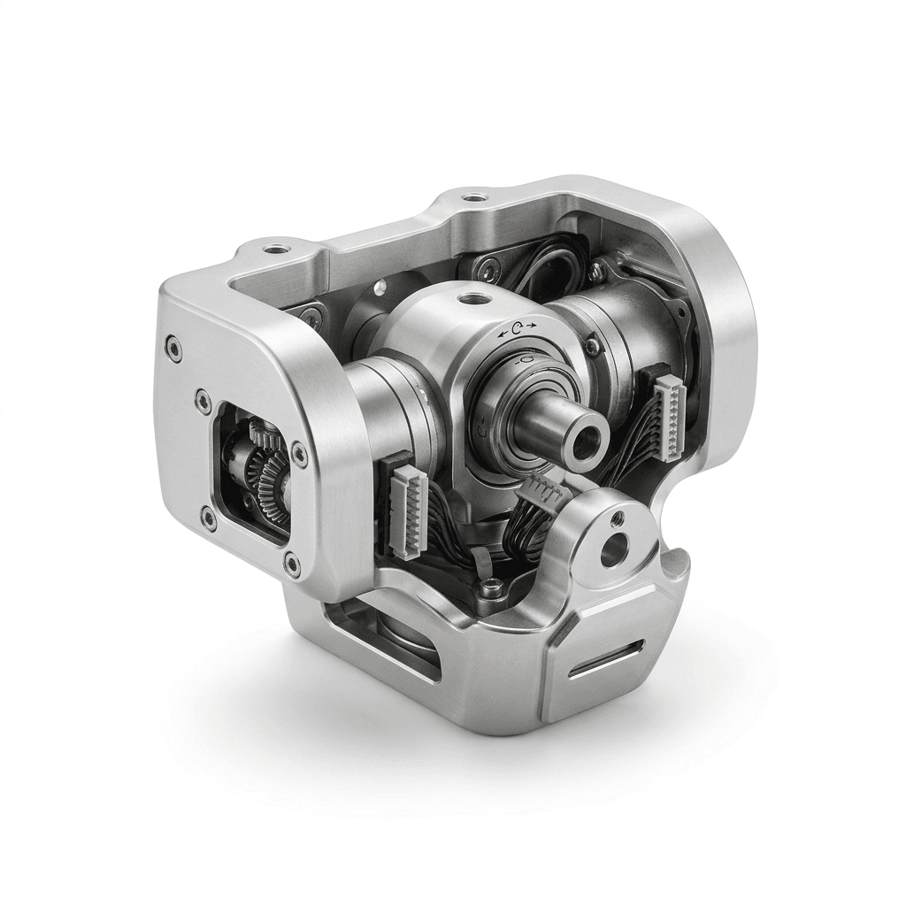
Humanoid bipedal robot 2-DOF pitch-yaw ankle joint actuator with dual high-response motors

Solution Highlights

  • Duty-cycle-aware joint selection by axis function
  • Compact integration with cable-routing and serviceability constraints
  • Risk controls for impact, thermal rise, and wiring reliability events

Common Use Cases

  • Commercial humanoid platforms
  • Biped locomotion research systems
  • Warehouse and factory mobile humanoids
  • Service humanoid pilot deployments

Implementation Focus

  • Joint assignment by axis demand, inertia, and failure consequence
  • Thermal and shock margins under repeated stop-go motion
  • Maintenance strategy tied to uptime and spare policy
  • Interface governance for motor, encoder, and reduction stack

Application Evaluation Matrix

Evaluation MetricTypical RangeBuyer Relevance
Axis-level fit confidencePer-axis validationPrevents late-stage redesign in full-body integration.
Peak torque class by axis35-120 Nm typical by shoulder/hip/knee scopeAligns module family to dynamic tasks without oversizing every joint.
Thermal rise budgetTarget delta-T defined by enclosure and duty profilePrevents thermal derating during long-duration motion cycles.
Backdrivability and reflected friction windowProject-specific target by control architectureDirectly impacts disturbance rejection, walking stability, and safety response.

RFQ Preparation Checklist

  1. Axis-level torque/speed and duty profile
  2. Weight and envelope constraints
  3. Control protocol and feedback needs
  4. Prototype timeline and test plan

Risk and Mitigation

  • One-size-fits-all module strategy: Use axis-specific selection and verification matrix.
  • Harness twist or abrasion in high-DOF joints: Lock cable routing and bend-radius constraints before EVT sample freeze.
  • Ground-impact events causing gearbox or bearing drift: Define impact-load test profiles and acceptance criteria at axis level.

Recommended Products

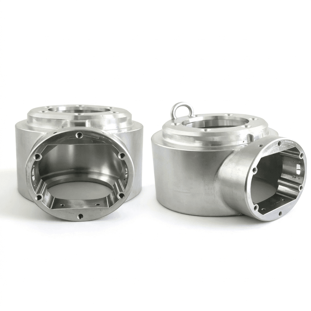
Dual-motor differential drive humanoid robot torso and waist joint assembly
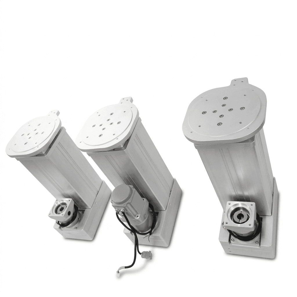
Parallel linear actuator driven bipedal humanoid hip joint mechanism with spherical linkages
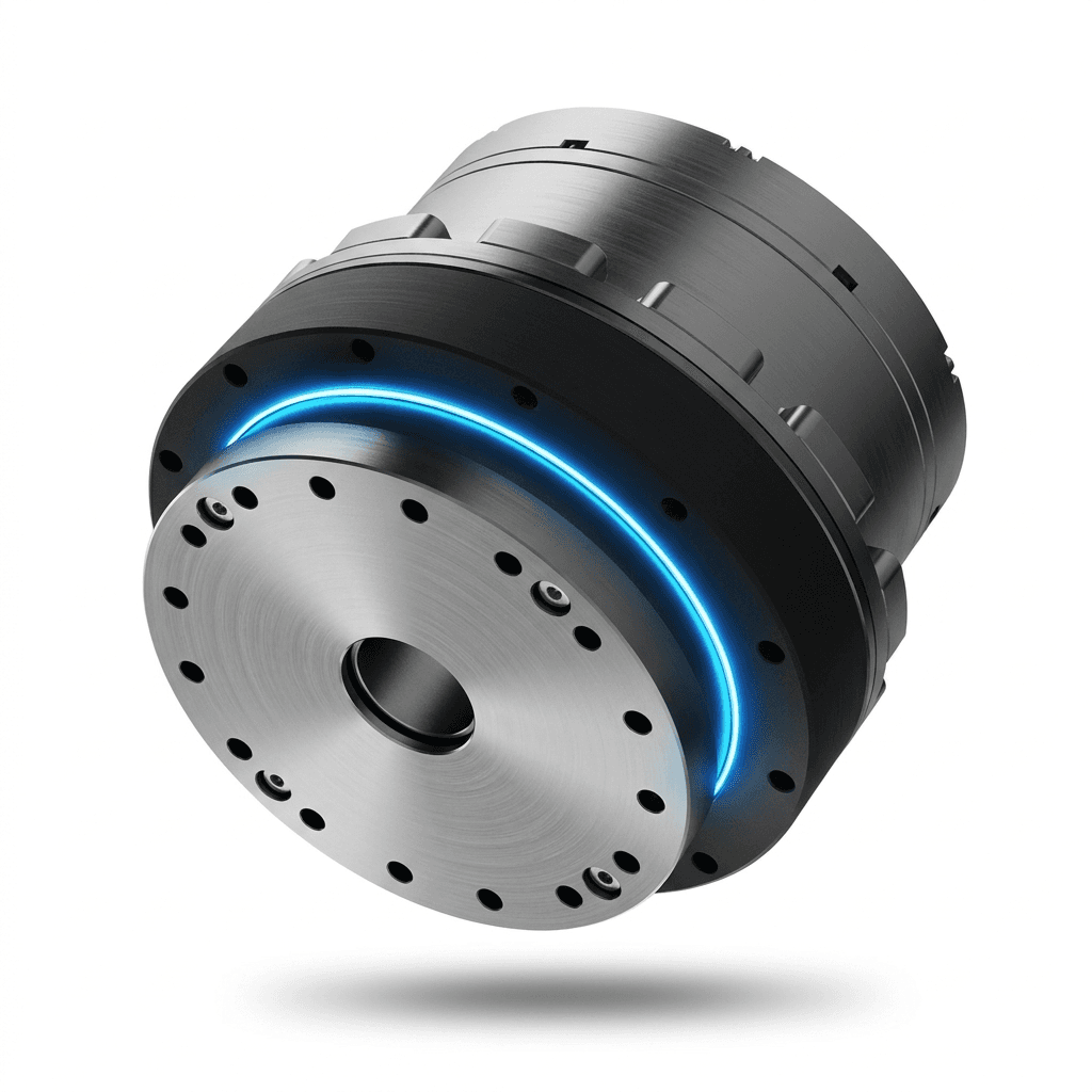
High-torque-density concentric planetary humanoid robot shoulder joint actuator

Buyer FAQ

Can one module family cover all humanoid joints?

Usually no. Multi-family selection by axis is recommended for balanced performance.

Do you support axis-by-axis BOM recommendations before prototype order?

Yes. After receiving load, speed, and envelope assumptions, we can propose a draft axis mapping with tradeoff notes.

Can we align thermal and impact validation criteria before tooling decisions?

Yes. We typically define pass/fail limits for thermal rise, impact recovery, and backlash drift before committing to ramp plans.

Related Resources

Inquiry Email

[email protected]

Open email app

Send target torque/speed, protocol, quantity, and delivery location.

Instant Chat

+86 18857971991

Direct response from our engineering team.