
AGV Arm Joint Actuator Integration for Industrial Automation Lines
For industrial mobile-arm integrators: estimate a load and DC power scenario, review missing evidence, and prepare a preliminary RFQ.
Request engineering reviewAGV Arm Integration Precheck
Published · Reviewed · Illustrative engineering models; measured component and machine data take precedence. Prepared by Robotic Joint Module. Review every six months or when cited standards, models or interfaces change.
Four integration decisions before selecting a joint
| Decision | Evidence and boundary | Action |
|---|---|---|
| Review the vehicle and arm as one application | Vehicle scope [S1], robot scope [S2], integration scope [S3]; no single component certificate proves application safety. [S1] [S2] [S3] | Assign an integrator to define interfaces, hazards, operating zones and release authority. |
| Budget energy as well as peak power | Repeated regeneration and cooling can limit operation even with adequate supply current. [S8] | Measure a representative cycle and the worst stop at high battery charge. |
| Separate motion synchronization from safety response | Clock alignment and safe-message supervision solve different problems. [S6] [S7] | Specify both trajectory timing and the complete protective response chain. |
| Qualify routing against the actual harness | Cable limits depend on product, free length and motion. [S10] | Review twist per metre, bend radius, shielding, connector strain and fatigue test conditions. |
Scroll horizontally on mobile devices to view all columns.
These are integration recommendations inferred from the sources and model boundaries. They are not certified architecture prescriptions or product performance claims.
Model, assumptions and known unknowns
Reproduce the precheck before using it to frame supplier questions.
| Output | Calculation and default assumption | Excluded / required before selection |
|---|---|---|
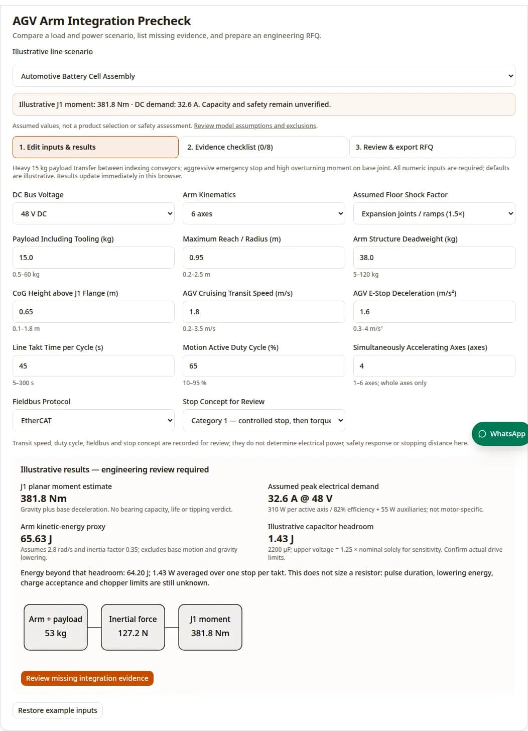
| J1 planar moment (Nm) | M = (0.45 × m_arm + m_payload) × 9.81 × reach + (m_arm + m_payload) × decel × K × CoG height. K = 1 / 1.5 / 2.2 for the three illustrative floor conditions. | No link-by-link acceleration, turning, coupled arm motion, chassis compliance, load direction combination or bearing rating. K is a sensitivity assumption, not a measured floor property. |
| DC current scenario (A) | P = active axes × 310 W / 0.82 + 55 W. I = P / nominal bus voltage. | 310 W/axis, 82% and 55 W are editor-selected assumptions, not actuator data. Transit speed and duty are recorded but do not predict power/RMS current. |
| Arm energy proxy (J) | J = 0.35 × (m_arm + m_payload) × reach²; E = 0.5 × J × 2.8². | Assumed inertia factor and 2.8 rad/s speed; no potential energy change, mobile-base energy or measured regeneration efficiency. |
| Capacitor headroom proxy (J) | E_cap = 0.5 × 0.0022 F × [(1.25 × V_nominal)² − V_nominal²]. | 1.25 × nominal is a sensitivity endpoint, not an approved operating or clamp voltage. Use actual capacitance, tolerance and minimum drive voltage limits. |
| Energy beyond capacitor headroom | max(0, E − E_cap); divide by takt for an illustrative one-stop-per-cycle mean. | No pulse rating, resistor value, battery charge acceptance or thermal release decision. Zero excess in this model is not proof that regeneration is safe. |
Scroll horizontally on mobile devices to view all columns.
Default worked example: 38 kg arm + 15 kg tool-inclusive payload, 0.95 m reach, 0.65 m CoG height, 1.6 m/s² deceleration and K = 1.5 give 381.8 Nm. Four active axes at 48 V give 32.6 A under the power assumptions. Energy is 65.63 J; 2200 µF from 48 to 60 V absorbs 1.43 J. These are reproducible arithmetic examples, not measured outcomes.
Reproduce the integration precheck
In a JavaScript-enabled browser, choose Automotive Battery Cell Assembly, retain all default inputs, and compare the displayed 381.8 Nm planar moment and 32.6 A assumed DC demand. The model and limits above explain every constant. Then change the scenario to review the evidence still needed for an RFQ. This supplier-authored software demonstration is not a physical load test, customer installation or safety assessment.
Keep responsibility boundaries explicit
| Owner | Responsibility | Evidence to exchange |
|---|---|---|
| Line integrator | Station clearance, transfer permissions, guarding and restart conditions | Hazard assessment, interlock truth table, timeout and reset tests |
| Vehicle supplier | Chassis loads, stability, navigation and battery/BMS limits | Support geometry, allowed forces/moments, supply and charge acceptance envelopes |
| Arm / joint supplier | Motion loads, drives, brakes, network modes and thermal limits | Torque-speed curves, combined bearing loads, safety manuals and brake test data |
| System integrator | Combined safety functions, fault behavior and site release | Validation report, worst-case stop tests and named acceptance owner |
Scroll horizontally on mobile devices to view all columns.
Do not assume the station PLC, navigation computer and motion controller share a safety rating. Define who detects each fault and which validated path reaches the actuator. [S3] [S4] [S7]
Mechanical loads: moment is a starting point
The scalar model aligns gravity and base deceleration in one adverse plane and assumes the arm mass acts at 45% of reach. Replace it with the actual mass distribution and motion histories for each mounting interface. Tooling, hoses and payload variation belong in the load case.
| Option | Potential benefit | Limit / verification |
|---|---|---|
| Integrated cross-roller support | Compact support for combined loading | Obtain actual static/dynamic limits, preload, mounting rigidity, bolt design and oscillatory-life method; no generic 720 Nm rating applies. |
| Spaced bearing pair | Layout can provide a useful moment arm | Consumes space and depends on separation, alignment and load sharing; architecture alone does not prove lower capacity. |
| External support / docking restraint | Can redirect loads into a qualified structure | Adds mass, installation work and docking complexity; verify load paths and fail states. |
| Shorter reach / stowed transit | Reduces some gravity and inertial lever arms | May reduce task access or throughput; check the remaining arm and vehicle load cases. |
Scroll horizontally on mobile devices to view all columns.
Bearing service hours are unknown: catalog rating, equivalent load factors, speed/load spectrum, lubrication and mounting details have not been supplied. A generic rating-life formula cannot validate this application. Vehicle tipping stability also needs total mass, support polygon, slope, steering and wheel contact data.
DC power: current, voltage drop and protection
| Nominal voltage | Current = P/V | Decision boundary |
|---|---|---|
| 24 V | 62.5 A | Higher current for the same power; check connector and harness limits. |
| 48 V | 31.25 A | Useful comparison point; actual charged and depleted battery levels matter. |
| 60 V | 25.0 A | Requires compatible drives, protection and transient margin; no blanket electrical safety classification is implied. |
Scroll horizontally on mobile devices to view all columns.
ΔV = 2 × L × I × ρ20 × [1 + α × (T − 20)] / A
For an illustrative copper loop: one-way L = 3.5 m, I = 55 A, ρ20 = 0.0178 Ω·mm²/m, α = 0.00393/°C and conductor temperature 65°C. The calculated drop is 2.02 V at 4.0 mm² or 3.23 V at 2.5 mm², excluding connector resistance. At 48 V the corresponding load voltages are 45.98 V and 44.77 V. A pass/fail verdict still needs the minimum battery voltage and drive input limit.
This resistance example does not establish ampacity. Apply the selected cable installation derating, ambient temperature, bundling, moving duty, connector ratings and protective-device coordination. Precharge also needs actual capacitance and resistor pulse energy: use a voltage-based completion check and fault timeout rather than assuming a universal delay.
Regeneration: separate pulse energy from average heat
Mechanical kinetic energy is ½ΣJω²; a descending load can add m·g·Δh. Calculate which drives share a bus and when base and arm regeneration coincide. Capacitor headroom uses the actual permissible voltage rise, not an arbitrary percentage. Confirm battery acceptance at full charge, cold conditions and BMS disconnect. [S8]
| Quantity | Known in precheck | Still required |
|---|---|---|
| Energy per event | Arm-only illustrative proxy | Measured trajectory, gravity lowering, concurrent axes/base, conversion efficiency |
| Pulse power and current | Unknown | Deceleration waveform and duration; chopper peak current and minimum resistance |
| Average thermal load | One-stop-per-takt arithmetic only | Full production duty, cooling, ambient, repeated stops and thermal shutdown behavior |
| Voltage margin | Illustrative capacitor endpoint only | Highest battery voltage, drive absolute/operating limits, chopper threshold/tolerance and transient overshoot |
Scroll horizontally on mobile devices to view all columns.
For the default proxy, 65.63 − 1.43 = 64.20 J exceeds capacitor headroom; spread over 45 s this is 1.43 W. The same energy released in 0.15 s would average 428 W during that interval. Neither value establishes the peak waveform or a complete resistor rating. The supplier guide requires validation on the actual system. [S8]
Safety functions: define behavior, then validate it
| Concept | Behavior | Boundary |
|---|---|---|
| Category 0 / STO-based concept | Removes torque-producing capability without a controlled powered stop | Motion may coast or fall under gravity. STO is not a mechanical brake or electrical isolation. |
| Category 1 / controlled stop then torque removal | Decelerates with power, followed by torque removal | Requires a validated sequence, fault response and gravity-axis holding arrangement. No universal ramp or brake delay applies. |
| Category 2 / controlled stop with power retained | Power remains available after the stop | Not an emergency-stop selection. Standstill monitoring and restart controls depend on application design. |
Scroll horizontally on mobile devices to view all columns.
Stop-category definitions and STO behavior are described by the drive manufacturer. [S9] [S11] Required PL/SIL follows the application assessment, not the keyword, industry label or presence of two wires. Check the full sensor–logic–communication–drive–mechanical chain and evidence for each safety function. [S3] [S7]
For gravity axes, establish holding capacity, response tolerances, wear checks, power-loss behavior and the consequences of a brake fault. Measure stop time and distance at adverse payload/posture/speed combinations. This page gives no safety distance or production release verdict.
Choose supported motion modes, then measure timing
| Option | Review first | Tradeoff |
|---|---|---|
| EtherCAT | Drive mode, Distributed Clocks support, cycle configuration and diagnostic capture | Precise synchronized node timing is available; it does not specify the full machine reaction time. |
| PROFINET | Controller/drive support, RT versus IRT capability, topology and scheduling | Can align with the plant ecosystem; verify the actual motion interface rather than assuming IRT from the protocol name. |
| CANopen | Supported drive profile, bus load, bitrate, PDO schedule and synchronization | May suit constrained networks; demonstrate that the configured traffic meets the required motion timing. |
Scroll horizontally on mobile devices to view all columns.
ETG describes Distributed Clocks synchronization significantly below 1 µs for supported nodes. That is a clock-alignment capability, not a blanket jitter limit for every software layer. [S6] Safety over EtherCAT adds safety-message supervision; ordinary motion data does not automatically inherit it. [S7]
Hollow-shaft routing: qualify every cable and tube
A torsion rating is usually expressed per metre of free cable. As an illustrative check, ±180° across 0.30 m equals ±600°/m; it is not equivalent to ±180°/m. Reducing a harness to a solid-shaft shear-strain formula cannot prove conductor or shield fatigue life. The CFROBOT8.PLUS example advertises ±360°/m for that series; the exact part and motion conditions still govern. [S10]
Review minimum bend radius, clamped versus free length, connector strain, bore clearance, abrasion, shielding and segregation with the cable supplier. Air tubes and safety conductors can set a stricter limit than the bus cable. Continuous rotation needs suitable rotary interfaces or a constrained motion strategy; finite cable loops have finite travel.
For cleanroom transfer, specify the customer particle test and equipment state. ISO 14644-1 classifies airborne cleanliness; it does not mandate PFPE grease, hermetic joint seals or a universal Class 3 robot. [S5]
Docking: separate positioning from permission to move
Allocate the error budget across vehicle localization, mechanical locators, chassis deflection, arm compliance, tool calibration and workpiece variation. Joint encoder resolution alone does not establish TCP repeatability or eliminate base tilt. Output feedback may reduce gearbox-related position error; validate the complete mechanical and control system under load.
Optical couplers and wireless links can carry process handshakes. Connection latency and alignment tolerance depend on the device and installation. Define stale-message detection, fault state, local motion supervision and supervised restart with the safety integrator; no universal 15 ms handshake or 50 ms freeze with guaranteed position accuracy is supported here. [S3] [S7]
Thermal duty and environmental qualification
Motion duty percentage is not RMS torque or RMS current. Obtain time histories for load, speed and dwell, then compare supplier thermal curves at the actual mounting interface and ambient. An enclosed mobile chassis can remove less heat than a catalog bench fixture. Monitor motors, drives, brakes, connectors and chopper components during the agreed production cycle.
Specify coolant exposure, ingress, vibration, ESD and cleanliness tests from the site requirements and exact component specifications. Magnet grade, seal choice, lubrication and encoder architecture do not establish a universal continuous temperature or positioning guarantee. Acceptance limits and derating remain pending until agreed with suppliers.
Three worked planning scenarios
Hypothetical scenarios using the tool presets; no customer deployments or measured production outcomes are claimed.
| Scenario and premise | Process / model result | Next decision |
|---|---|---|
| Battery handling: 15 kg payload, 38 kg arm, 0.95 m reach, 48 V, four active axes | Default model: 381.8 Nm planar moment, 32.6 A assumed DC demand, 65.63 J arm energy proxy. | Request load-spectrum, chassis stability and regen measurements; do not select a bearing from the moment alone. |
| FOUP planning: 5 kg payload, 24 kg arm, 0.85 m reach, 48 V, three active axes | Smooth-floor proxy: 142.2 Nm and 24.8 A. Fab cleanliness, vibration and positioning remain unknown. | Agree particle and handling acceptance criteria before choosing harness, seals or docking hardware. |
| SMT replenishment: 3 kg payload, 14 kg arm, 0.60 m reach, 24 V, two active axes | Proxy: 60.7 Nm and 33.8 A. Changing only nominal voltage to 48 V halves the model current. | Compare supply compatibility and measured power before changing voltage; confirm trajectory/network needs and stop design. |
Scroll horizontally on mobile devices to view all columns.
For a warehouse arm with longer reach, test both stowed transit and workstation transfer. If a load case cannot be supported within the vehicle and joint limits, compare fixed-pedestal handling, mechanical docking restraint or shorter-reach transfer rather than assuming a larger actuator resolves stability.
Risk, cost and scenario fit
Qualitative review prompts; no invented occurrence scores or RPN ranking.
| Risk | Missing evidence | Mitigation or alternative |
|---|---|---|
| Misuse: treating the precheck as a safety release | Whole-application hazard assessment, safety-function validation and stop tests | Keep estimates in the RFQ only; require the named integrator to approve acceptance evidence. |
| Power loss during regeneration | Worst stop at high charge, BMS disconnect and chopper pulse/thermal capacity | Validate alternate energy path; adjust motion profile or hardware within supplier limits. |
| Mounting damage or tipping | Combined load spectrum, support polygon, fasteners and slope/turn cases | Review structure and stability; restrain at station or stow during transit where appropriate. |
| Cost: larger harness and moving interfaces | Routing, connectors, shielding and maintenance access | Compare total installed cost including cable replacement, rotary interfaces and downtime; no price estimate is asserted. |
| Cost: safety/network integration | Available certified functions, controller modes, engineering and validation effort | Choose compatible supported components and budget commissioning, documentation and training. |
| Scenario mismatch: precision / cleanroom task | Customer accuracy, vibration and particle acceptance results | Compare local fixtures, station calibration or fixed handling; qualify cleanliness at the actual operating state. |
| Unexpected restart after link recovery | Timeout, reset authority, stale-message rejection and station clearance tests | Require the validated restart sequence; link restoration alone must not be treated as permission. |
Scroll horizontally on mobile devices to view all columns.
Sources, dates and evidence limits
Public sources checked 2026-11-12. Catalog scopes and manufacturer guidance are not full compliance assessments.
Use the applicable editions and complete texts with the integrator. Public catalogs support scope and edition information, not unviewed clause numbers. Manufacturer examples apply to their products. Unknown acceptance values remain unknown; they are not filled with generic performance claims.
[S1] ISO 3691-4:2023
Driverless industrial trucks and their systems; public scope only. Check applicability to the selected vehicle and operating environment.
Checked 2026-11-12
[S2] ISO 10218-1:2025
Industrial robot safety; the catalog does not establish a particular actuator rating or system certification.
Checked 2026-11-12
[S3] ISO 10218-2:2025
Industrial robot applications and cells; integration responsibilities require the full standard and application risk assessment.
Checked 2026-11-12
[S4] A3 industrial robot standards directory
R15.08 covers design, integration and use of industrial mobile robots. Directory lists Part 3 as 2026; no clause-level interpretation is asserted here.
Checked 2026-11-12
[S5] ISO 14644-1:2015
Air cleanliness classification by particle concentration; does not specify a universal joint seal, lubricant or fab acceptance class.
Checked 2026-11-12
[S6] EtherCAT Technology Group: technology
Distributed Clocks support precise node synchronization; network timing is separate from overall safety response.
Checked 2026-11-12
[S7] EtherCAT Technology Group: safety
FSoE is a safety protocol; ordinary process data and a wireless connection do not by themselves provide a validated safety function.
Checked 2026-11-12
[S8] Synapticon: braking chopper integration guide
Chopper capacity depends on regenerated power and repeated thermal load; actual-system testing is required. Product-specific guidance, not a universal resistor rating.
Checked 2026-11-12
[S9] Schneider Electric: Safe Torque Off
STO inhibits torque production; the motor can coast. It does not define stopping time, gravity-axis holding or electrical isolation.
Checked 2026-11-12
[S10] igus: CFROBOT8.PLUS torsion cable
Particular cable series supports torsion per metre. Verify the exact part, bend radius, speed, temperature and tested life; do not generalize to an entire harness.
Checked 2026-11-12
[S11] Schneider Electric: stop categories
Defines stop Categories 0, 1 and 2. Select the application safety functions separately; category labels do not supply timings.
Checked 2026-11-12
Acceptance gates and records
| Gate | Record / owner | Release condition |
|---|---|---|
| Design review | System integrator: interfaces, loads, safety concept, acceptance plan | All unresolved safety requirements assigned and closed before hazardous testing. |
| Controlled electrical checks | Qualified electrical team: polarity, bonding/protection, insulation where applicable, precharge and supply faults | Results meet the selected equipment manuals and agreed electrical design. |
| Mechanical and low-energy trials | Arm/vehicle suppliers: mounting, restrained motion, payload and routing | Clearance and combined loads validated against actual component limits. |
| Safety and fault validation | Safety integrator: stops, brakes, gravity loads, communication/power loss, reset and restart | Complete-function evidence accepted; protective distances derived from validated worst cases. |
| Production-cycle qualification | Site owner: thermal duty, repeatability, cleanliness and interlock behavior | Agreed test duration/conditions met; deviations closed; maintenance and change-control records handed over. |
Scroll horizontally on mobile devices to view all columns.
Integration questions by decision area
Electrical
Why compare 24 V with 48 V?
For equal electrical power, doubling voltage halves current. With the same resistance this quarters I²R loss. It does not determine conductor area: route length, thermal installation, fuse coordination and actual peak current still matter.
Does a 48 V battery always remain at 48 V?
No. Obtain minimum loaded and maximum charged voltage, BMS charge/discharge limits and transient behavior. Compare these with the drive and chopper operating ranges, including cable drop and regeneration.
Can the battery absorb all braking energy?
Only if its charge acceptance, state of charge, temperature and connection state permit it. Verify the worst combination and the alternate energy path. A disconnected BMS must be included in the fault review.
Does the displayed average energy rate size a resistor?
No. Energy divided by takt describes a one-stop-per-cycle average. Peak power, pulse energy, minimum allowable resistance, chopper current, cooling and lowering loads remain separate requirements.
Controls
Is EtherCAT mandatory?
No. Match controller and drive support to trajectory bandwidth and synchronization needs. Compare the supported EtherCAT, PROFINET or CANopen modes, configuration tools and diagnostics. The protocol name alone does not establish a cycle time.
Does Distributed Clocks timing equal safety response?
No. Clock alignment helps coordinated sampling and outputs. Protective response also includes the sensor, safety logic, safe communication watchdog, drive response and physical stopping behavior. Measure the complete chain.
Can ordinary Wi-Fi be a docking safety interlock?
Ordinary connectivity alone is insufficient. Separate process coordination from the safety function. A qualified integrator must specify the safety architecture, validated timeouts, link-loss response and supervised restart.
What happens after a docking link fails?
The application must enter its validated fault state and inhibit unauthorized transfer or restart. Whether to stop the arm, stop the base or maintain a particular state depends on the hazard assessment and available safety functions.
Safety
Does STO actively brake the arm?
STO prevents torque production. The arm can coast or move under gravity and external loads. Holding brakes, mechanical restraints and their sequencing require separate validation. See the Schneider Electric STO reference [S9].
How do stop Categories 0, 1 and 2 differ?
Category 0 removes actuator power without a controlled powered stop; Category 1 uses a controlled stop followed by power removal; Category 2 retains power after a controlled stop. Category 2 is not an emergency-stop selection.
Does the checklist certify the system?
No. It records items the user says have been reviewed. Required PL/SIL, validation evidence and release authority belong to the complete application assessment. A certified drive does not certify the mobile manipulator or station.
How is stopping distance established?
Use worst-case measured stop behavior across payload, posture, speed, floor, supply and faults with the applicable safeguarding method. This precheck intentionally provides no protective distance, reaction-time or safe-release calculation.
Mechanical
Does J1 moment prove that the vehicle will not tip?
No. Check the full-system center of gravity and support polygon, wheel contact, slopes, turns, acceleration and arm motion. The model omits vehicle mass and geometry and therefore cannot assess tipping stability.
Does a cross-roller bearing guarantee life?
No. Obtain the actual combined-load ratings, preload, housing stiffness, mounting tolerances and load spectrum. Static shock limits and oscillatory service need review. A bearing architecture alone cannot establish service hours.
Can a short hollow-shaft loop support continuous rotation?
A finite torsion-rated cable has finite angular travel. Check twist per metre and bend limits for every cable and tube. Continuous rotation may require qualified rotary interfaces; a solid-shaft strain equation cannot establish harness fatigue life.
Commissioning
What should an RFQ contain?
Send tool-inclusive payload, CAD and postures, measured motion and power profiles, battery and drive voltage limits, bearing interfaces, network modes, required safety functions, environmental limits, takt and acceptance tests. Mark unknowns explicitly.
Request an integration review
Use the tool’s RFQ step to copy your scenario and pending evidence. Include measured power/motion data, mechanical drawings, acceptance targets, timeline and quantity. If these are unavailable, send the known requirements and mark the rest pending.
Inquiry Email
Send target torque/speed, protocol, quantity, and delivery location.