
Engineering decision guide · AGV / AMR mobile manipulators
AGV Arm Joint Actuator Integration Guide
Choose the power bus, harness route and motion network together, then release the assembled machine only after measured commissioning and safety validation.
For mechanical, electrical and controls integrators. Compare options, reproduce the estimates and identify the evidence needed from each supplier. Updated .
Guide chapters
1. Four integration decisions to settle first
Power: use the full voltage envelope
48V can reduce losses at equal input power, but full-charge voltage, loaded voltage, regeneration and ampacity determine the actual harness and drive selection.
[S5]Cabling: use the exact cable rating
Internal routing reduces exposed loops. Verify bend radius, twist from neutral and free length against the selected cable; geometry alone cannot predict fatigue life.
[S9]2. Method, assumptions and evidence limits
This guide combines public standards scopes, versioned software documentation and manufacturer examples with explicitly stated engineering calculations. Catalogue pages verify scope and edition; they do not provide a clause-level compliance review. Recommendations below are integration checks, not certified designs.
| Layer | Known or modeled here | Required before release | Owner |
|---|---|---|---|
| Mechanical | Payload, geometry and load-case checklist | Exact interface, bearing load envelope, preload and vehicle stability analysis | Mechanical integrator + joint supplier |
| Power | Cable resistance at an assumed 50°C | RMS current, ampacity, fuses, connectors, minimum/maximum bus voltage and regeneration | Electrical integrator + battery/drive suppliers |
| Motion network | Illustrative frame budget | ESI/EDS, firmware, actual PDO traffic and timing trace under load | Controls integrator |
| Safety | Applicable-scope references and hazard prompts | Risk assessment, required integrity, device certificates/manuals and system validation | Machine integrator + safety specialist |
Published by Robotic Joint Module (RJM). First published . Evidence reviewed on the same date. Next review due by , or earlier after source, firmware or model changes. Send corrections through engineering contact.
Scope: industrial AGV/AMR arms in controlled working areas. Public-access, medical, explosive-atmosphere and passenger-carrying applications need additional domain assessment. No supplier-specific mounting torque, bearing life, cable endurance or safety response time is established here.
3. Traceable evidence and version boundaries
Sources checked on 2026-11-12. ISO robot design, robot application and industrial-truck scopes must be considered separately. The drive-safety reference includes the 2026 amendment; installed devices may have certificates to earlier editions that require assessment.
| Source | Evidence strength & date | Supported use | Boundary |
|---|---|---|---|
[S1] ISO 3691-4:2023 | Official scope; published 2023-06, revision in development. | Driverless industrial truck systems, including AGVs/AMRs. | Check truck classification and operating environment. Power-source requirements are outside this scope. |
[S2] ISO 10218-1:2025 | Official scope; published 2025-02. | Industrial robot design before integration. | Explicitly excludes hazards from mobility on trucks/mobile platforms; does not establish complete mobile-machine safety. |
[S3] ISO 10218-2:2025 | Official scope; published 2025-02. | Industrial robot applications and cells. | Assess applicability alongside mobile-platform standards; this catalogue is not a clause-level conformity assessment. |
| Official catalogue; edition 2.1 published 2026-10-30. | Safety-related drive subsystem design, integration and validation. | A device certificate covers its specified functions/configuration. Dual channels alone do not establish SIL or PL for the machine. | |
[S5] IEC 60204-1:2016 | Official catalogue; amendment 1:2021 also listed. | Machine electrical equipment, bonding, protection and documentation. | Consult the applicable adopted edition. Nominal voltage and a cable drop calculation cannot establish PELV or electrical compliance. |
| Official profile overview; accessed 2026-11. | Drive state machine, control/status words and motion modes. | Actual supported objects, PDO mappings, scaling and cycle periods come from each drive manual and ESI/EDS. | |
| Official technology explanation; accessed 2026-11. | Hardware Distributed Clocks can provide sub-microsecond device synchronization. | This is device-clock alignment, not a bound on ROS execution, host latency or complete motion response. | |
| Version-specific official documentation; accessed 2026-11. | Read/update/write loop, scheduler configuration and determinism. | Real-time kernel and permissions improve scheduling; timing must be measured on the deployed hardware under load. | |
| Manufacturer specification context; accessed 2026-11. | Some named cable variants support twist ratings up to ±360°/m. | A family maximum is not a universal cable rating or installed-harness cycle-life guarantee. | |
| Manufacturer application guide, V1.1, 2022-05. | Explains gravity-axis sag during torque removal and brake closing. | An example of drive-specific behavior; use the exact drive/brake manual and validate the load-holding function. |
4. Mechanical interface: drawings before frame labels
A frame label does not define a bolt pattern, fastener torque or allowable moment. Obtain the supplier drawing and loading envelope. Check the tool interface separately from the actuator-to-chassis mounting interface; an ISO 9409-1 tool flange label does not define every joint base mounting.
| Check | Why it changes selection | Evidence to request |
|---|---|---|
| Mass and center of gravity | Payload, gripper and link masses act through different lever arms | Mass model with extended/folded and worst stopping poses |
| Vehicle acceleration, turn and floor events | Base motion adds load and can threaten tipping stability | Measured route accelerations and support-polygon analysis |
| Mount, bolts and locating features | Preloaded friction joints, pilots and pins have different load paths | Approved drawing, material, fit, surface and tightening procedure |
| Bearing loading and life | Combined moments, oscillation, lubrication and duty alter life | Supplier calculation for the exact bearing and load spectrum |
Reproducible illustration: a 5 kg point payload at 0.85 m contributes 5 × 9.81 × 0.85 = 41.7 N·m of static moment. This excludes arm/tool mass and acceleration. Add arm and gripper mass, acceleration and worst stopping poses before sizing the joint or bearings. Check whole-vehicle stability separately.
5. Hollow-shaft routing: twist is measured from neutral
Use the cable maker’s permitted twist per unit free length and its bending, temperature and endurance conditions. For symmetric ±180° motion, centered neutral installation means 180° maximum excursion. The full end-to-end sweep is 360°, a different quantity. A homogeneous-shaft strain equation cannot establish stranded-cable service life. [S9]
| Option | Useful when | Trade-off / failure condition | Validation |
|---|---|---|---|
| Internal hollow bore | The installed cable envelope fits the bore and available free length | Hidden abrasion, heat and difficult replacement; fittings may dominate clearance | Inspect full travel under twist, bend and thermal load |
| External dress pack | Access and replaceability are priorities or internal free length is insufficient | Exposed loop and swept-envelope collision risks | Test against racks, docking hardware and tool changes |
| Rotary transmission interface | Continuous rotation is necessary | Current, contact noise, bandwidth, safety-channel and maintenance limits | Qualify the exact interface with the drive/network supplier |
Illustration, not a cable recommendation: with a selected rating of 180°/m, a 180° excursion requires at least 1.0 m of uniformly twisting free length. At 360°/m it would require 0.5 m, provided the exact cable permits that rating in the intended conditions. Bore-area fill is (bundle OD / bore ID)² × 100%; a 13.5 mm bundle in a 25 mm bore gives 29.2%. A 40% example target does not prove clearance, heat dissipation or fatigue performance.
6. DC power, conductor loss and EMC
Compare architecture at equal DC input power. Doubling voltage halves current and quarters I²R loss for unchanged cable resistance. Then check actual battery, drive and connector limits. Nominal 48V alone establishes neither PELV nor freedom from electrical hazards. [S5]
Calculation assumptions: copper ρ20 = 0.0175 Ω·mm²/m, α = 0.00393/°C, conductor temperature 50°C, one-way length L = 3.0 m and instantaneous DC input current I = 55 A through one lumped feeder. R = 2Lρ20[1 + α(T−20)]/A; ΔV = IR; P = I²R. These are illustrative material/model inputs, not an ampacity table.
| Area (mm²) | Loop resistance (Ω) | Drop (V) | Drop at nominal 48V | Peak line loss (W) |
|---|---|---|---|---|
| 2.5 | 0.0470 | 2.58 | 5.4% | 142.0 |
| 4.0 | 0.0293 | 1.61 | 3.4% | 88.8 |
| 6.0 | 0.0196 | 1.08 | 2.2% | 59.2 |
| 10.0 | 0.0117 | 0.65 | 1.3% | 35.5 |
At 4 mm² this model gives 1.61 V drop and 88.8 W instantaneous loss. Thermal acceptance still needs RMS duty, insulation, ambient temperature, bundling, connector and fuse data. Compare battery minimum under load minus cable/connector losses with the drive undervoltage threshold. A 5% drop budget is only an example design budget. The rows show instantaneous algebra at an assumed conductor temperature; they are not recommendations for continuous 55 A service. Distributed axis loads need a segment-by-segment model.
Precharge and protection
Use total capacitance and the permitted inrush envelope to select resistor pulse energy, bypass timing, contactor and fuse coordination. A resistor’s continuous wattage alone does not establish precharge suitability.
Bonding and shielding
Document protective bonding, functional bonding and signal returns separately. Follow the drive and cable EMC instructions for shield termination. Use the supplier acceptance method for each DC bonding and high-frequency shielding path.
Have a battery envelope and current profile ready? Request a power and harness review. Include the drive limits and wiring drawing with your request.
7. Regeneration: size from energy and peak power
Account for rotational/linear kinetic energy and gravity release during lowering. Establish the BMS charge-acceptance envelope and the disconnected-battery case. A braking chopper is one possible solution; select hardware compatible with the actual drive and voltage range.
| Quantity | Assumptions | Reproducible result | Limit |
|---|---|---|---|
| Capacitor headroom | C = 2,400 µF; 48V rising to 58V | ½ × 0.0024 × (58² − 48²) = 1.272 J | Chosen voltage limits must come from the real hardware |
| Residual energy | Assumed 16.5 J returned; no battery absorption | 16.5 − 1.272 = 15.228 J | 16.5 J is a scenario input, not a measured arm benchmark |
| Average during stop | 15.228 J released in 0.15 s | 101.5 W average during that interval | This is not peak power; peak waveform remains unknown |
| Long-term average | 15.228 J once every 10 s | 1.52 W average | Pulse energy, repeated stops, cooling and fault duty still govern |
For a chosen clamp voltage, P = V²/R describes an active resistor’s dissipation. It is not enough to choose R: respect minimum resistance/current limits, switching thresholds, pulse-energy curves and thermal protection for the selected drive.
8. Fieldbus: choose from the complete traffic schedule
| Dimension | EtherCAT CoE | Classical CANopen | Selection check |
|---|---|---|---|
| Motion profile | CiA 402 objects through CoE when supported | CiA 402 when supported | Verify mode support and actual ESI/EDS; profile support is not feature equivalence |
| Model line rate | 100 Mbit/s for the modeled Fast Ethernet link | 1 Mbit/s assumed in this estimate | Verify physical network and usable rate, topology and cable length |
| Timing | Hardware Distributed Clocks where supported | SYNC-driven schedules and CAN arbitration | Measure device synchronization separately from host/command latency |
| Traffic | Multiple axes can share process-data frames | More PDOs consume additional frames | Count actual bytes, frames, diagnostics, retries and deadlines |
CiA describes the drive state machine and command/status exchange. ETG describes device clock synchronization; neither gives a universal axis-count cutoff or host scheduling guarantee. [S6][S7]
Example schedule: six CANopen axes × two 8-byte PDOs × 135 modeled bits/frame + one 55-bit SYNC = 1,675 bits/cycle. At 1 Mbit/s and a 1 ms cycle, occupancy is 167.5%; at 2 ms it is 83.8%. The 135-bit framing/stuffing allowance is a model assumption. Additional PDOs or traffic can invalidate the latter schedule. Arbitration delays frames; it is not an Ethernet-style collision model.
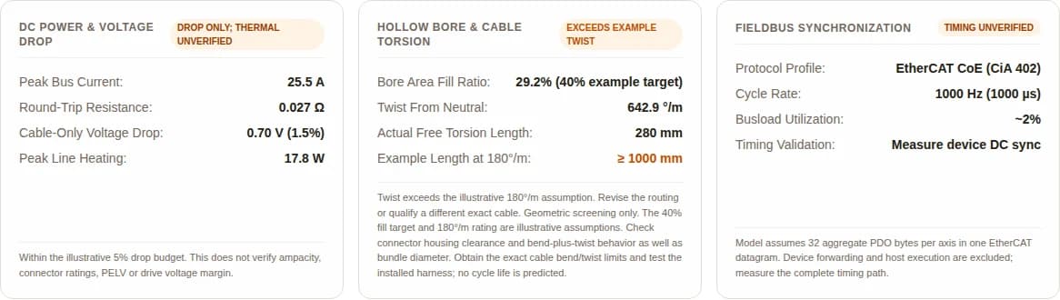
The estimator uses 32 aggregate PDO bytes per EtherCAT axis in a single datagram: 38 bytes Ethernet framing and inter-frame gap, 2 bytes EtherCAT header, 10 bytes datagram header, data and 2 bytes Working Counter. See the Beckhoff EtherCAT technology datasheet, section 2.2. Serialization alone excludes device forwarding and host execution. To reproduce the CANopen example, select six axes, CANopen and a 1,000 or 2,000 µs cycle. To reproduce the 55 A cable example, set two concurrent axes at 27.5 A each, 3.0 m and 4 mm². Select Logistics Mobile Manipulator to reset the separate execution-capture example. Its 280 mm free length exceeds the illustrative twist assumption and needs revision or exact cable qualification.
9. ROS 2: validate the hardware contract
The reference documentation is ros2_control Jazzy, checked 2026-11. Controller Manager executes a read/update/write loop and attempts real-time scheduling; kernel choice and permissions influence determinism. Measure execution and missed deadlines on the target IPC under representative load. No fixed latency is guaranteed by enabling PREEMPT_RT. [S8]
Before torque enable
Confirm gear ratio, encoder reference, joint direction, units, command mode and joint limits with the supplier. Test one restrained axis first. Store the ESI/EDS, firmware and hardware-interface versions with the configuration.
When data is late or lost
Specify stale-command detection and drive watchdog behavior, then inject communication failures. Avoid generic packet extrapolation. Set command expiry and fault reactions from measured timing and the exact drive/controller contract. Ordinary controller fault handling must coordinate with the independently validated machine safety functions.
10. Safety functions and integration risks
STO suppresses motor torque and does not mechanically hold a gravity-loaded arm. For a spring-applied, power-released brake, removing coil power allows the brake to close after its mechanical delay. Select and validate the handover using the exact drive/brake manual; measure behavior under load with suitable restraint. [S4][S10]
The diagram is a concept review, not a wiring or timing specification. SS1 variants and fault paths must follow certified device capabilities. CiA 402 Quick Stop alone is not SS1. Determine required integrity, response times, brake monitoring and reset behavior from the machine risk assessment; test power loss as well as a commanded stop.
| Failure / trigger | Consequence | Mitigation to investigate | Acceptance evidence |
|---|---|---|---|
| Low battery + concurrent acceleration | Drive undervoltage or uncontrolled process interruption | Budget all losses and adjust power architecture/motion demand | Loaded voltage and thermal measurements at worst operating point |
| Twist, bend or chafe beyond cable limits | Conductor/shield failure and intermittent signals | Revise routing and validate exact cable specification | Full-travel harness tests plus inspection criteria |
| Traffic overload or late host command | Missed deadlines and stale motion commands | Reduce traffic, retime loop and configure fault response | Network trace, host latency and injected-failure record |
| Regeneration with no battery sink | Bus overvoltage and loss of controlled deceleration | Qualified energy-management path and thermal protection | Maximum-voltage and repeated-stop testing |
| Torque removed before load is held | Gravity motion and dropped load | Drive-specific brake/load-holding architecture | Worst-case stop, brake and supply-loss validation |
| Loose mount or adverse base pose | Structural damage or vehicle tipping | Validate mount load path and combined stability | Approved drawing, torque record and loaded stop/turn tests |
11. Commissioning: record evidence at each hold point
The following is an integration workflow, not a substitute for equipment manuals. Use the supplier’s permitted electrical tests; isolate sensitive electronics as instructed before any insulation test.
1. Cold checks
Confirm polarity, protection, connector pinout, bonding and restrained mechanical assembly. Use approved test voltages and isolation arrangements.
2. Network without motion
Load the correct ESI/EDS, verify drive states and object scaling, and record actual PDO traffic.
3. Single-axis commissioning
Follow the supplier phasing procedure, verify direction and limits, then run low-speed tests with load restraint.
4. Combined duty and timing
Run representative arm/base motions at loaded battery limits; measure bus voltage, heat, network and host timing.
5. Fault and safety validation
Inject communication loss and supply faults under the approved procedure; validate stop, brake, scanner-zone and reset behavior.
6. FAT/SAT handover
Keep configuration and test records; verify installation-specific routes, floors, loads and protection before release.
12. Three illustrative application decisions
Hypothetical engineering scenarios. The values are planning inputs; no customer deployment or validated performance result is claimed.
Warehouse tote arm
Premise: 48V, six axes, 2.8 m harness; 1 ms desired loop.
Process: Model voltage loss, check the cable neutral reference, and compare PDO schedules.
Decision: retain a 1 ms requirement only if the actual drive/network timing passes; a bore that fits the bundle can still fail twist limits.
Cleanroom transfer arm
Premise: Seven axes, compact internal routing; contamination restrictions.
Process: Compare internal cable access, lubricant/seal specifications and particle qualification with the facility owner.
Decision: require application-specific cleanliness evidence. A general industrial cable or torque rating cannot establish cleanroom suitability.
Heavy mobile handling arm
Premise: High payload and repeated lowering with a possibly disconnected BMS.
Process: Model gravity/kinetic energy and inspect combined vehicle stability in the worst extended pose.
Decision: choose energy-management and structural hardware after supplier load/thermal data; a nominal 48V label is insufficient.
Optional: reproduce the preliminary estimates
Use these illustrative inputs to compare assumptions after reading the decision guide. No cable endurance, thermal approval, stopping distance or safety certification is calculated.
AGV Arm Joint Actuator Integration Calculator
Quantify DC bus voltage drop, hollow-shaft cable twist per metre, and fieldbus busload across 48V/24V power distribution networks and EtherCAT/CANopen topologies.
Illustrative application presets — not qualified configurations
Standard 48V DC bus, 6-axis arm with 5 kg payload, 2.8 m cable harness routed through hollow bore, 1 ms EtherCAT CoE loop.
Preliminary integration estimates
Within the illustrative 5% drop budget. This does not verify ampacity, connector ratings, PELV or drive voltage margin.
Twist exceeds the illustrative 180°/m assumption. Revise the routing or qualify a different exact cable. Geometric screening only. The 40% fill target and 180°/m rating are illustrative assumptions. Check connector housing clearance and bend-plus-twist behavior as well as bundle diameter. Obtain the exact cable bend/twist limits and test the installed harness; no cycle life is predicted.
Model assumes 32 aggregate PDO bytes per axis in one EtherCAT datagram. Device forwarding and host execution are excluded; measure the complete timing path.
Evidence checklist (0/6 confirmed by you)
Self-reported; does not authorize operationAssumptions: ρ20 = 0.0175 Ω·mm²/m, α = 0.00393/°C, copper at 50°C. Lumped feeder model: full modeled current over the entire stated length. Segmented loads, connector loss, ampacity, battery sag and safety validation excluded.
13. Integration questions by responsibility
Architecture & mechanics
What must be specified before choosing a joint module?
Record payload and tool mass, reach, arm mass distribution, base acceleration, duty cycle, mounting stiffness and operating environment. Request manufacturer load limits and interface drawings; payload alone cannot establish joint or vehicle stability.
Is hollow-shaft routing always better than an external dress pack?
Internal routing reduces exposed loops but makes inspection and cable replacement harder. An external dress pack can be preferable when the bore, free twist length or thermal clearance is insufficient. Compare the complete swept envelope in both cases.
How is the angle for a cable twist check defined?
Use maximum excursion from the installed neutral cable position. For symmetric ±180° travel installed neutral at the center, use 180°, not 360°. Verify the cable maker uses the same neutral reference and test convention.
Can a shear-strain equation predict millions of cable cycles?
No. A stranded multicore cable is not a homogeneous elastic shaft. Select the exact cable using its bend and twist ratings, temperature and endurance conditions, then validate the installed routing. The estimator does not predict fatigue life.
Power & electrical
Does a nominal 48V battery establish PELV?
No. Full-charge and regenerative voltage, supply isolation, fault behavior and applicable electrical requirements must be assessed. Nominal 48V is an architecture choice, not a declaration of shock protection.
When does 48V reduce cable losses compared with 24V?
At equal DC input power and equal conductor resistance, doubling voltage halves current and reduces I²R loss to one quarter. This ideal comparison excludes efficiency changes and does not prove a particular wire is thermally adequate.
Should motor phase current be entered into the estimate?
No. Enter battery-side DC input current per axis for the relevant motion segment. Motor phase current differs with PWM duty, speed and power factor. Include all concurrent loads when reviewing the real supply.
Can the battery always accept regenerative energy?
No. Check the BMS charge-current envelope and disconnected or full-battery states. Compare stopping energy and peak power with bus storage and the selected drive energy-management hardware before choosing a braking resistor.
Fieldbus & software
Is EtherCAT mandatory for a six-axis arm?
No. Choose from the actual PDO map, supported drive modes, cycle deadline and measured timing. EtherCAT can provide more communication headroom; CANopen can be suitable when its complete traffic schedule fits the required motion.
What does an estimate over 100% CAN utilization mean?
The assumed frames take longer to serialize than the available cycle. That schedule is infeasible even before adding diagnostics and retries. Reduce traffic, increase cycle time or change architecture, then verify the actual trace.
Does sub-microsecond Distributed Clock alignment guarantee ROS timing?
No. Device clocks and host scheduling are different timing layers. Measure read/update/write execution, frame deadlines and drive watchdog response on the target computer. The reference software discussion uses ros2_control Jazzy.
Can a generic ROS configuration certify safe fault handling?
No. Confirm joint directions, units, limits and mode transitions with the actual hardware interface. Communication-loss and stale-command responses need application tests; ordinary ROS control and CiA 402 Quick Stop are not safety-rated functions by themselves.
Safety & commissioning
Does STO hold a gravity-loaded joint in place?
No. STO suppresses drive torque and can allow a loaded axis to fall. A spring-applied, power-released brake closes when coil power is removed, with a mechanical delay. Its holding capability and the drive-specific handover must be validated under restraint.
How should stop and brake timing be selected?
Determine the stop, brake and torque-removal sequence from the risk assessment and device safety manual. Measure worst-case stopping and brake behavior with the required load, temperature and supply conditions; no universal delay is supplied here.
May a 500V insulation test be applied to an assembled actuator?
Only use test voltages and connection arrangements explicitly permitted by the equipment manufacturer. Isolate electronics, encoders, surge suppressors and other sensitive circuits as instructed. A generic high-voltage test can damage integrated electronics.
What evidence is needed before production release?
Retain the approved interface drawing, electrical protection and energy calculations, measured timing/thermal records, harness routing tests and system safety-validation record. The integrator owns the release decision; completing this page checklist is not an authorization to operate.
14. Assign the next action and evidence owner
Mechanical lead
Send the joint supplier the complete load spectrum, mounting drawing and route acceleration data. Request allowable combined loads and installation instructions.
Electrical / controls lead
Send the battery envelope, DC current profile, harness layout and PDO map. Request drive voltage/energy limits, protection requirements and firmware-specific configuration.
Machine / safety lead
Define the integrated base-arm risk assessment, required safety functions and acceptance tests. Record the stop/brake validation and installation release decision.