
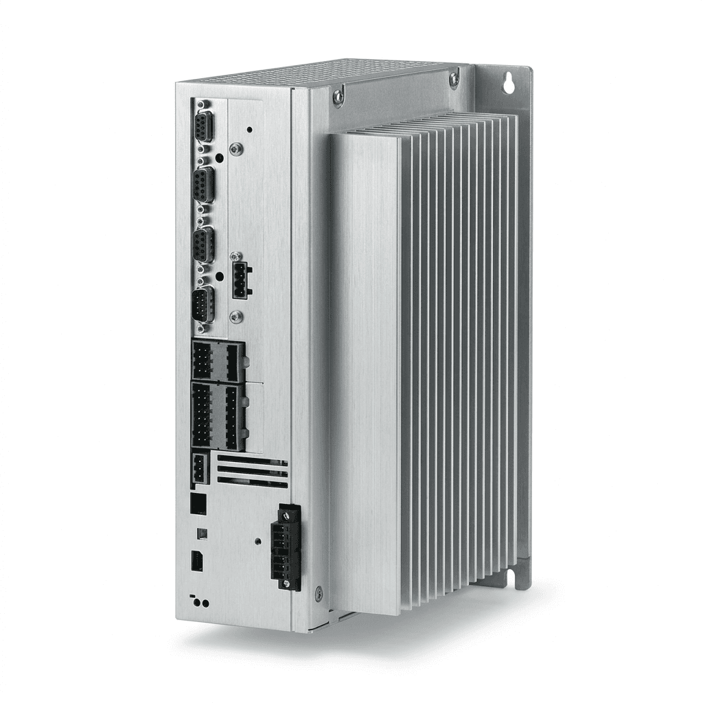
Robot Joint Module Thermal Management & Derating Guide
A comprehensive guide for engineers and procurement teams on understanding thermal derating, continuous torque limits, and heat mitigation strategies in robotic joint modules.
In the push for higher payload-to-weight ratios in cobots and humanoids, "peak torque" has become the headline spec on most datasheets. However, when a robot fails during a continuous task or loses precision after 30 minutes of operation, the culprit is rarely a lack of peak torque—it's thermal throttling.
For procurement teams and systems engineers, buying a robot joint module without understanding its thermal derating profile is a massive risk. This guide breaks down how heat affects joint performance and how to specify thermal requirements in your next RFQ.
Scope, Audience, and Limits
Last reviewed: 2026-07-18. This guide is written for global OEM buyers, robotics engineers, and sourcing teams evaluating integrated robot joint modules for cobots, humanoids, mobile manipulators, and high-duty automation axes.
Use it as a procurement and engineering checklist, not as a substitute for supplier-specific thermal modeling. The derating curve below is illustrative; final sizing still requires the supplier's continuous torque curve, duty-cycle test conditions, thermal sensor locations, mounting method, and a bench test that matches your real ambient temperature and motion profile. For broader sourcing criteria, pair this guide with the robot joint module OEM selection guide and the integrated joint module with EtherCAT/CANopen product family.
The Physics of Heat Generation in Joint Modules
Robot joint modules are densely packed systems containing a frameless torque motor, a harmonic or planetary gearbox, dual encoders, and often a built-in servo drive. This compact design is excellent for footprint but terrible for heat dissipation.
- $I^2R$ Losses (Copper Losses): The primary source of heat. As current flows through the motor windings to generate torque, the resistance of the copper wire creates heat. Since heat scales with the square of the current, doubling the torque requirement quadruples the heat generated.
- Iron Losses (Eddy Currents & Hysteresis): Occur in the magnetic steel core of the motor as the magnetic field rapidly changes direction.
- Friction: Mechanical heat generated by the reduction gear and bearings.
If the internal temperature exceeds design limits, the control system must forcefully reduce power output to prevent permanent damage—a process known as thermal throttling or derating. Furthermore, if NdFeB (Neodymium) magnets exceed their Curie temperature limits, they suffer irreversible demagnetization, permanently reducing the module's torque capability.
Visualizing the Thermal Derating Curve
A proper supplier must provide a derating curve, not just a single "Max Operating Temperature" number. The curve below illustrates how available continuous torque drops as the ambient temperature rises.
Engineering Visualization: Typical Continuous Torque Thermal Derating Curve
Notice how the module can sustain 100% continuous rated torque up to the "knee" temperature (usually 40°C). Beyond that, the controller must proportionally reduce current to prevent winding failure. If your factory floor hits 50°C in summer, your robot just lost a significant percentage of its payload capacity.
Comparing Thermal Mitigation Strategies
When an off-the-shelf module cannot handle your duty cycle without derating, you must implement mitigation strategies. Below is a comparison of common engineering approaches. Treat the ranges as early-stage screening values; require vendor test data before releasing a production BOM.
| Mitigation Strategy | Mechanism | Cost Impact | Design Complexity | Maintenance Need | Typical Effectiveness |
|---|---|---|---|---|---|
| Passive Heat Sinking | Finned aluminum housings or mounting to large robot frames | Low | Low | Zero | 10-20% improvement in continuous torque |
| Thermal Interface Materials (TIMs) | High-conductivity gap pads inside the module housing | Low | Medium | Zero | Eliminates hot spots; crucial for driver ICs |
| Active Air Cooling | Integrated micro-fans pushing air across fins | Medium | Medium | High (dust/filter cleaning) | 40-60% improvement; ruins IP rating |
| Liquid Cooling | Circulating coolant through a jacket around the stator | High | Very High | High (leaks, pumps) | 100%+ improvement; used in heavy industry |
| Predictive Thermal Firmware | Adjusting trajectories or slowing movements before hard throttling | Low | High | Zero | Prevents sudden shutdowns, improves stability |
| Oversizing the Module | Buying a larger joint module and running it at a lower duty cycle | High | Low | Zero | 100% effective but adds weight to the robot arm |


If the axis still fails the thermal margin after these checks, compare standard robotic joint module product families against a joint module OEM customization path before locking the mechanical envelope.
Procurement Validation Checklist for Thermal Specs
Do not accept a simple "Operating Temperature: -20°C to 80°C" line item. Use this checklist during the OEM evaluation phase:
- Request the Derating Curve: Demand a chart showing continuous torque vs. ambient temperature.
- Verify Test Conditions: Was the continuous torque tested with the module in free air, or bolted to an aluminum heat-sink plate? (Suppliers often use a massive aluminum plate during testing to artificially inflate the continuous torque spec).
- Define the Duty Cycle: Submit your exact motion profile (acceleration, cruise, deceleration, dwell) and ask the supplier to simulate the expected temperature rise.
- Confirm Driver Protection Logic: Ask exactly what happens when the temperature threshold is reached. Does the joint shut down completely (fault state), or does it enter a controlled reduced-torque mode?
- Check Sensor Locations: A good integrated module will have multiple thermistors (one on the motor windings, one on the driver PCB). Verify that the control loop reads both.
Frequently Asked Questions (FAQ)
Q: Can I use peak torque as my operating baseline?
A: Absolutely not. Peak torque is typically only sustainable for 1 to 5 seconds before thermal safety limits are breached. Always size your application based on continuous torque.
Q: Does the IP rating affect thermal management?
A: Yes. An IP67-rated joint module is tightly sealed against water and dust, which also means it traps heat inside. Fully sealed modules require excellent internal thermal bridging to the outer housing to survive high duty cycles.
Q: What is the Curie temperature, and why does it matter?
A: The Curie temperature is the point at which permanent magnets lose their magnetic properties. For the NdFeB magnets commonly used in robot joints, operating above 120°C - 150°C (depending on the grade) can cause permanent demagnetization, meaning the motor will never produce its rated torque again, even after cooling down.
Q: If my robot operates in a cold environment (e.g., -10°C), can I run the module harder?
A: Thermally, yes, the motor windings can handle more current. However, extreme cold increases the viscosity of the gearbox grease, which increases internal friction and can cause premature mechanical wear.
Sources and References
These references set standards context only. They do not replace a supplier's robot joint module derating curve, insulation-class declaration, or application-specific safety validation.
- IEC 60034-1: Rotating electrical machines - Rating and performance; useful context for duty cycles and thermal rating language. IEC Webstore
- IEEE Standards Association: Standards portal for applicable electrical machine, insulation, and test-method references during specification review. IEEE SA
- ISO/TS 15066: Collaborative robot technical specification; relevant when thermal derating changes speed, payload, stopping behavior, or collaborative application assumptions. ISO
Inquiry & Custom Solutions
If your robot platform is struggling with thermal throttling, or if you need an integrated joint module rated for continuous high-duty-cycle operation, our engineering team can help. We specialize in custom thermal bridging and predictive derating firmware.
- Compare product families: Robotic joint module products
- Review customization options: Joint module OEM customization
- Email: [email protected]
- WhatsApp: +86 18857971991
Categories
More Posts
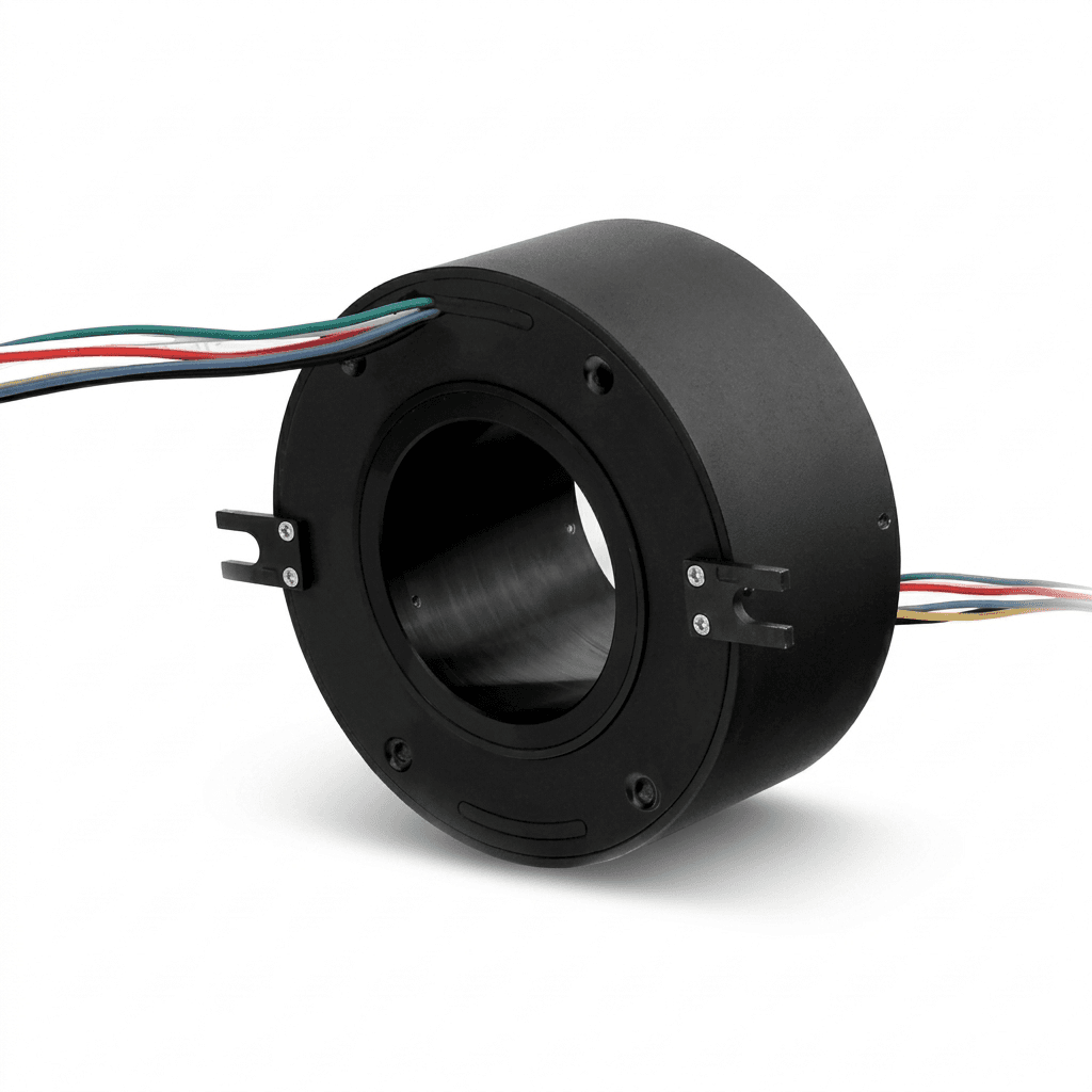
Hollow-Shaft vs Solid-Shaft Robot Joint Modules: A Sourcing Guide (2026)
An engineering and procurement guide to evaluating hollow-shaft versus solid-shaft robotic joint modules for humanoid, cobot, and industrial robot arms.

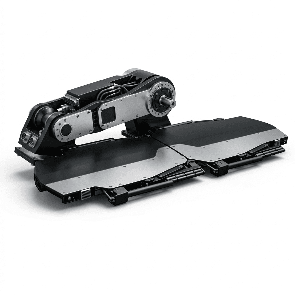
Functional Safety (STO & SBC) in Integrated Joint Modules: A Procurement Guide
Evaluate functional safety, STO, and SBC requirements for robotic joint modules, with sourcing checks for engineers and procurement teams before a vendor RFQ.
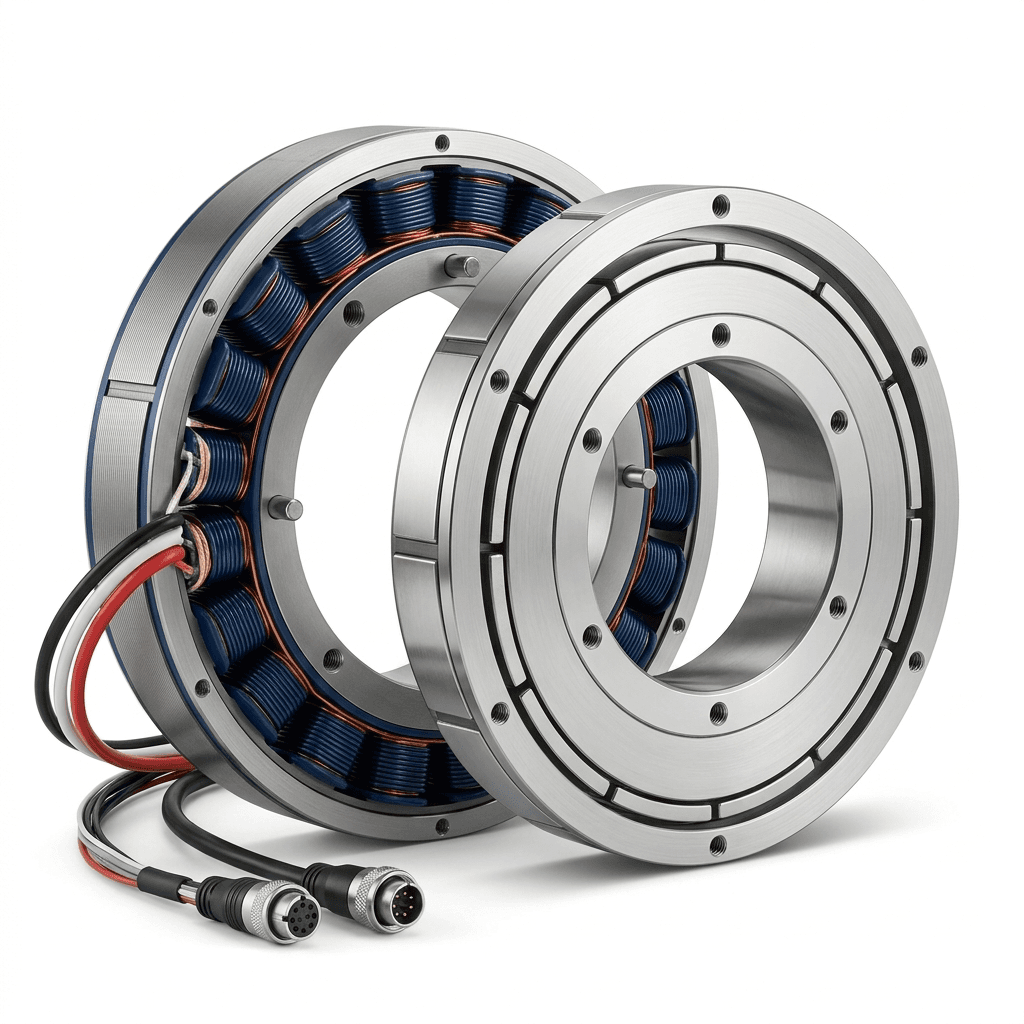
Frameless Torque Motor Guide: Outrunner vs Inrunner for Robotic Joints
A practical comparison of outrunner and inrunner frameless torque motors for cobot, humanoid, and precision motion applications.