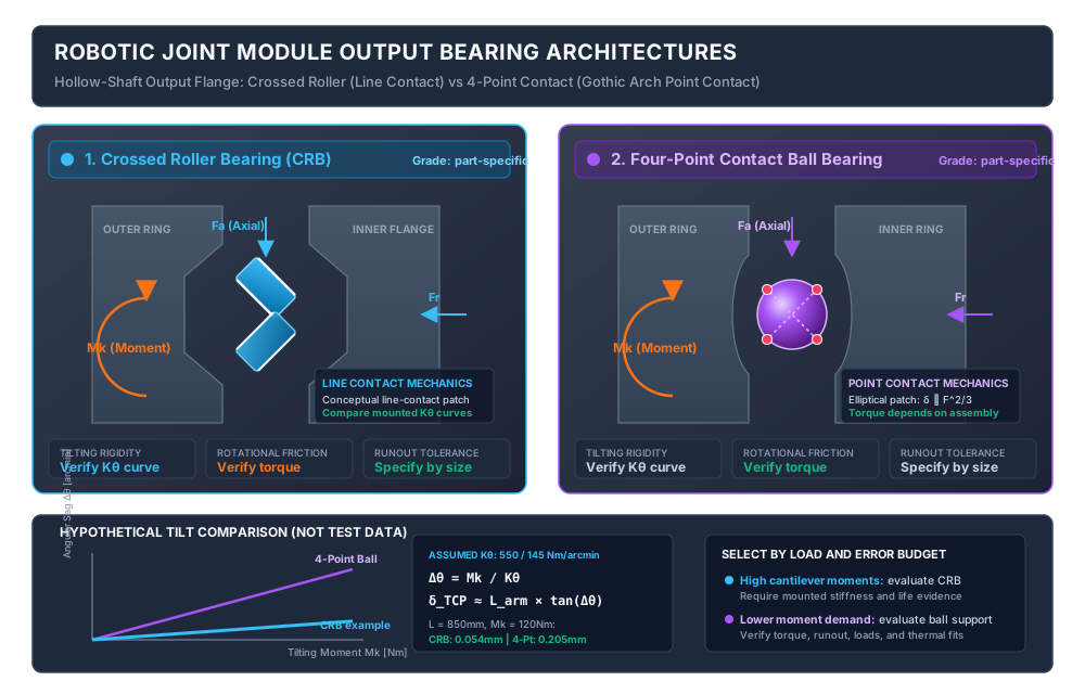
Crossed Roller vs Four-Point Contact Bearings in Hollow-Shaft Robotic Joint Modules: Tilting Moment Rigidity, Runout Tolerances, Preload, and Sourcing Guide
Compare crossed roller vs four-point contact bearings for robot joints. Evaluate tilting stiffness, runout, preload and thermal fits, then prepare your RFQ.
Crossed roller vs four-point contact bearings: shortlist by the joint's worst-case tilting moment, tool center point (TCP) sag allowance, starting and running friction torque, operating temperature range, and housing accuracy. In an integrated hollow-shaft robotic joint module, the output support carries the external forces and bending moments assigned to it by the assembly load path. Even with a low-backlash harmonic drive or cycloidal reducer, bearing and housing compliance can cause angular deflection at the end-effector.
Crossed roller bearings use cylindrical rollers arranged with alternating, approximately perpendicular axes. Their line contacts can provide high moment stiffness in a compact envelope. Four-point contact ball bearings use curved raceways that permit different contact combinations as load direction changes. They can be attractive where friction, mass, packaging, and cost matter. Neither topology has a universal stiffness multiplier, runout grade, thermal advantage, or price ratio: compare specific part numbers in their mounted condition.
This guide gives robot mechatronics engineers, hardware architects, and OEM procurement managers a framework to specify output bearings for hollow-shaft joint modules. It covers tilting stiffness calculations, runout acceptance criteria, preload selection, thermal fits, and supplier qualification.
Published and reviewed: November 9, 2026. Scope: Global OEM sourcing; English-language engineering guidance. The worked examples below are hypothetical calculations, not measured product performance or customer case studies. They support early comparison; supplier-specific data and mounted assembly tests are required before design release.
If you are configuring a modular actuator BOM, explore our robotic joint actuator catalog or submit your axis loading profiles for an application engineering RFQ review.
1. Executive Summary & Sourcing Trade-Off Matrix
The output bearing operates under combined radial force Fr, axial force Fa, and tilting moment Mk. Selection should identify whether compliance, load capacity, starting torque, or installation limits dominate the joint design. A bearing's precision grade describes specified geometry; it does not by itself establish stiffness or load capacity.
Use this trade-off matrix before freezing joint envelope dimensions. A QJ four-point bearing and a thin-section four-point bearing are separate product families: shared terminology does not establish interchangeability or suitability as a moment support.
| Engineering & Procurement Metric | Crossed Roller Bearing (CRB) | Four-Point Contact Ball Bearing | Sourcing & Design Verification Required |
|---|---|---|---|
| Contact geometry | Alternating roller orientations with line contacts | Ball contacts on curved raceways; active contacts depend on loading and clearance | Confirm contact angle, ring construction, and permitted combined loads for the exact series. |
| Tilting moment rigidity | Often attractive for compact, stiff output supports | Can suit moment loads when the specific design and envelope permit | Request mounted moment-versus-tilt curves; do not apply a generic multiplier. |
| Starting and running friction | Preload, seals, grease, and mounting distortion can increase torque | May offer low torque, but multiple active contacts and preload can increase friction | Compare identical temperatures, speeds, seals, and lubrication conditions. |
| Running accuracy | Available in multiple precision grades | Also available in precision grades | Specify part size, grade, datum, and radial/axial runout limits. |
| Housing and shaft accuracy | Thin rings can reproduce seat distortion | Thin-section ball bearing rings can also distort | Obtain dimensional and geometrical tolerances from the selected manufacturer. |
| Thermal fit sensitivity | Clearance and preload change with ring temperatures and seat restraint | Also sensitive to differential expansion | Review shaft, housing, and ring temperatures together. |
| Dynamic and static capacity | Depends on geometry, material, preload, and load distribution | Depends on the same factors and permitted contact conditions | Compare approved equivalent-load methods and rating bases. |
| Shock exposure | Roller edge loading and permanent indentation need evaluation | Ball contacts can also suffer permanent indentation | Check peak load combinations and post-event torque/runout acceptance. |
| Axial envelope | A single bearing can replace a wider paired support in some designs | A single-row design can also save axial space | Compare installed assembly dimensions, including retainers and seals. |
| Procurement cost | Precision grade, preload, and inspection affect price | The same factors can outweigh topology-level savings | Obtain matched-volume quotes with equivalent acceptance documentation. |
| Application fit | Strong candidate for heavily cantilevered axes | Candidate where the verified stiffness and friction budgets allow | Select by load spectrum and error budget, rather than axis number alone. |
2. Fundamental Contact Mechanics: Hertzian Line vs Point Contact
The contact geometry affects elastic deformation, but contact geometry alone cannot predict the stiffness of an assembled joint. Raceway conformity, rolling element size and count, preload, ring flexibility, bolt pattern, and housing restraint all matter.
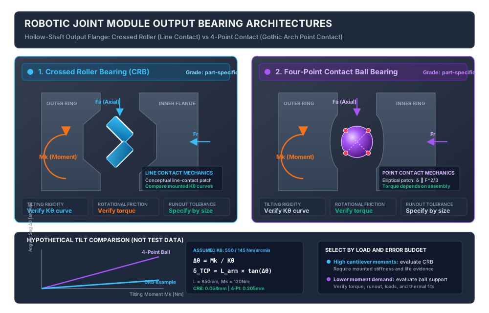
Conceptual engineering schematic, not to scale. The deflection comparison uses the assumed stiffness inputs in Section 2.2; it is not a measured bearing curve or a universal topology ranking.
2.1 Contact Deformation and What It Can Tell You
Under a normal contact force, a ball and raceway form an approximately elliptical contact patch. In an ideal Hertzian point-contact model, elastic approach scales with force to the power of two-thirds. Roller contact is spread along a finite length, and practical roller models also account for end geometry and nonuniform load distribution.
These contact models explain why designers investigate roller supports for high stiffness in limited space. They do not prove that one catalog bearing is three or four times stiffer than another. A stiffness comparison needs the same moment range, preload state, fixture compliance, and loading direction. Ask whether a quoted value is tangent stiffness at one operating point or a secant value over a specified load interval.
2.2 Tilting Moment Stiffness & Tool Center Point (TCP) Sag
For perpendicular forces acting on a simple lever arrangement, an illustrative overturning moment is:
Mk = Fpayload × Larm + Fr × Loffset
Use consistent units, such as newtons and meters. Do not count the same payload force twice; actual robot loads require the vector sum of downstream masses, external forces, and inertial moments for each pose.
For a locally linear response, angular deflection is:
Δθ = Mk / Kθ
Here Mk is in N·m, and tilting stiffness Kθ may be supplied in N·m/arcmin or N·m/rad. Convert the resulting angle to radians before calculating TCP displacement:
δTCP = Larm × tan(Δθ) ≈ Larm × Δθ
Worked Engineering Comparison
Consider an illustrative shoulder-joint load case with a reach of 850 mm and a tilting moment of 120 N·m. Assume two candidate bearing assemblies with the following stiffness values. These are chosen inputs for demonstrating the arithmetic; no catalog part or measured test is represented.
- Case A: Assumed crossed roller bearing assembly
- Tilting stiffness:
550 N·m/arcmin, equivalent to approximately1.89 × 10^6 N·m/rad. - Angular deflection:
120 / 550 = 0.218 arcmin = 6.35 × 10^-5 rad. - TCP deflection:
850 × 6.35 × 10^-5 ≈ 0.054 mm, or 54 µm.
- Tilting stiffness:
- Case B: Assumed four-point contact bearing assembly
- Tilting stiffness:
145 N·m/arcmin, equivalent to approximately4.98 × 10^5 N·m/rad. - Angular deflection:
120 / 145 = 0.828 arcmin = 2.41 × 10^-4 rad. - TCP deflection:
850 × 2.41 × 10^-4 ≈ 0.205 mm, or 205 µm.
- Tilting stiffness:
If the bearing-only TCP allocation were 0.10 mm in this load case, the minimum required stiffness would be approximately 1.02 × 10^6 N·m/rad, or 297 N·m/arcmin. The assumed Case A clears that allocation and Case B does not. This is an input-based screening decision, not proof that all crossed roller bearings pass.
Gearbox, flange, housing, link, and other joint deflections consume the remaining TCP budget. For a serial arm, project their contributions through the robot kinematics rather than simply multiplying one joint's sag by six.
3. Dynamic Load Capacity, Static Safety Factors & Service Life
Selecting a bearing solely on static holding ability can miss fatigue, lubrication, or shock limitations. ISO 281:2007 addresses dynamic ratings and rating life; ISO 76:2006 addresses static ratings. Neither supplies a complete approval method for every robot duty cycle.
3.1 Equivalent Dynamic Load Under Moment Loading
In robotic joints, the output bearing rarely experiences pure radial load or axial thrust. The equivalent dynamic load P must come from the selected manufacturer's combined-load calculation or engineering assessment. Do not reuse load factors from a different bearing series.
A rough force-couple scale is Fcouple ≈ 2 × Mk / dm, where dm is the effective contact pitch diameter. With moment in N·m, use diameter in meters to obtain newtons. This relation is only a geometric screening aid: it is not an ISO-approved equivalent dynamic load formula, and adding it to radial and axial loads can misrepresent the internal load distribution.
For a four-point contact bearing, verify whether combined radial, axial, and moment loading is permitted in the intended support arrangement. The active contacts and load distribution change with load direction, clearance, and preload. Raceway contact truncation or excessive misalignment requires manufacturer evaluation rather than a generic load-factor substitution.
3.2 Basic Rating Life
For a constant equivalent load and speed, the conventional basic rating-life expression in hours is:
L10h = [10^6 / (60 × n)] × (C / P)^p
Cis the basic dynamic load rating andPis the dynamic equivalent load, expressed in matching force units.nis rotational speed in rpm.p = 10/3for roller bearings;p = 3for ball bearings.
L10 represents a statistical fatigue-life basis associated with 90% reliability under the applicable assumptions. It is not a guarantee of complete joint service life. Confirm that catalog ratings use a compatible reference distance or revolution basis before comparing them.
Robot joints often reverse through small angles, dwell under load, and experience variable speeds. An average rpm alone cannot capture lubrication replenishment, false brinelling, contamination, corrosion, or electrical damage. Submit the motion spectrum, angular travel, dwell time, and temperature history so the supplier can assess these additional failure modes.
3.3 Static Safety Factor and Shock Resistance
The basic static safety factor is fs = C0 / P0, where C0 is the basic static load rating and P0 is the applicable static equivalent load. The required minimum depends on loading uncertainty, acceptable permanent deformation, operating accuracy, and the manufacturer's guidance.
Do not infer a universal collision-safe threshold from fs or from contact-stress reference values. Emergency braking and accidental impact can create different force paths and local peaks. Record the worst load combinations, obtain supplier acceptance, and define what must be inspected after an overload. A bearing static calculation does not establish robot collision safety or a safety-function response time.
4. Running Accuracy, Runout Tolerances & Sensor/Gearbox Integration
In an integrated joint module, the output support may locate an absolute encoder ring and a reducer flange. Determine the actual datum chain from the assembly drawing: some reducers have their own output bearings, so the proposed external bearing can otherwise create unintended overconstraint.
4.1 Specify Runout by Part Size and Datum
ISO 492:2023 specifies dimensional and geometrical characteristics and tolerances for radial rolling bearings within its scope. A class name alone does not define a universal micrometer limit. Values depend on bearing dimensions, parameter, design, and the applicable specification. Ask how the manufacturer applies the standard to its crossed roller or thin-section product.
Use this acceptance table instead of treating a ball-versus-roller topology as a precision grade:
| Acceptance Item | What the RFQ Must Define | Evidence to Request |
|---|---|---|
| Bearing identity | Exact part number, bore, outside diameter, width, and drawing revision | Controlled drawing and certificate of conformity |
| Precision class | Agreed standard edition or manufacturer-specific tolerance specification | Parameter-level tolerance table for that size |
| Radial running accuracy | Ring being rotated, datum, measuring location, and limit | Recorded radial runout and setup description |
| Axial running accuracy | Reference axis, measuring radius, applied measuring load, and limit | Axial face runout trace and fixture details |
| Mounted flange accuracy | Actual bolt pattern, tightening procedure, and seating conditions | Assembly-level total indicated reading (TIR) |
| Encoder track alignment | Track concentricity, face wobble, and sensor gap budget | Encoder mounting drawing and gap measurements |
| Repeatability after assembly | Reinstallation method and permitted change | Before/after mounting inspection records |
4.2 Impact on Off-Axis Encoders
For an idealized single-readhead angular track, a small eccentricity e at track radius Rtrack gives a first-harmonic geometric error scale of approximately e / Rtrack radians. Actual magnetic or optical encoder error depends on its sensing architecture, interpolation, alignment, and calibration.
For a hypothetical track radius of 35 mm:
e = 10 µmgives0.010 / 35 × 206265 ≈ 58.9 arcseconds.e = 2 µmgives0.002 / 35 × 206265 ≈ 11.8 arcseconds.
These are assumed eccentricities, not guaranteed errors for a precision class. A pure circular eccentricity produces radial TIR of approximately 2e, but a measured TIR can also contain form error and fixture effects. Do not automatically equate catalog bearing runout with encoder track eccentricity.
A 58.9 arcsecond angle corresponds to about 0.243 mm at an illustrative 850 mm lever length. Its contribution to a robot's position error still depends on encoder location and kinematics. Multiple readheads or calibration may reduce some error components; obtain the encoder manufacturer's mounting limits and verify assembled angular error.
4.3 Impact on Strain-Wave Gear Engagement
Precision strain-wave gearheads require alignment between the wave generator, flexspline, and circular spline according to the reducer manufacturer's drawing. Depending on the support arrangement, flange runout and housing deflection can disturb tooth contact or introduce additional loading.
A high bearing precision class cannot alone guarantee reducer alignment. Allocate a tolerance budget across the bearing, seats, flange, gear interfaces, and mounting bolts, then measure the assembled result. Keep unloaded runout and load-induced tilt as separate acceptance items: a joint can pass one and fail the other.
5. Preload Selection, Friction Torque & Thermal Fits
Zero clearance or preload can reduce lost motion under reversing loads, but excessive preload increases friction and contact loading. Some architectures can tolerate controlled positive clearance; the correct choice follows the stiffness, heat, and life budgets.
5.1 Preload Classifications Are Manufacturer-Specific
Do not translate codes such as C0, C1, C2, CC0, or CN between suppliers without their definitions. A code can describe a clearance group, a preload option, or another characteristic in a particular catalog. It does not establish a universal negative-clearance window.
Specify the delivered clearance or preload range, how it is measured, and whether it applies before or after mounting. Ask how fits and bolt tightening change the operating state. Compare a low-preload option and a higher-stiffness option using measured moment-deflection and torque curves, rather than selecting preload solely from the joint number.
5.2 Rotational Friction Torque Qualification
Bearing friction includes contact effects, rolling and sliding losses, lubricant drag, seals, and preload. Starting torque differs from running torque and varies with dwell, temperature, speed, grease fill, and assembly distortion. A simple friction coefficient cannot reliably predict the complete mounted behavior.
For hand-guided collaborative joints, friction can mask external torque estimation and increase the current needed for motion. Request cold-start, room-temperature, and hot-running torque data under comparable loads. Record torque versus angular position to identify periodic tight spots. A four-point contact bearing can also develop substantial friction if its contacts, seals, or preload are unsuitable.
To compare candidates, keep grease type and fill, seal arrangement, rotation speed, temperature soak, and fixture identical. Separate bearing torque from reducer and seal drag where practical. The motor's thermal budget must include the actual operating losses rather than an unverified topology-level torque range.
5.3 Differential Expansion in Aluminum Joint Housings
As an illustrative first-order model, take steel expansion as 12 × 10^-6 /K and aluminum expansion as 23 × 10^-6 /K. These are assumed coefficients, not material certificates. Ring temperature differences and seat interference can change clearance and preload in either bearing topology.
Scenario A: Warmer inner ring. If an unconstrained steel diameter of 100 mm is 40 K warmer than a comparable outer-ring reference, its differential diametral growth scale is:
100 mm × 12 × 10^-6 /K × 40 K = 0.048 mm = 48 µm
This is a diametral growth estimate, not a direct prediction of internal radial clearance. Raceway angle, ring dimensions, restraint, fits, and temperatures govern the resulting preload. Do not add this value directly to a supplier's micrometer clearance specification.
Scenario B: Cold aluminum housing. For a 120 mm seat cooled 35 K below assembly temperature, the free differential diameter change relative to steel is:
120 mm × (23 - 12) × 10^-6 /K × (-35 K) = -0.0462 mm = -46.2 µm
The negative sign indicates that the aluminum seat contracts more than the steel ring. The resulting interference and ring distortion depend on initial fit, wall thickness, bolt restraint, and contact conditions; the full 46.2 µm is not automatically transmitted to the raceway.
Mitigation options include revised fits, a reviewed steel sleeve, controlled preload, or changes to the thermal path. Specify bore and shaft fit tolerances separately, together with roundness, cylindricity, and perpendicularity. An ISO IT size-tolerance grade does not by itself specify these geometrical errors. Have the bearing supplier approve the mounting design, then measure torque and temperature after cold and hot soaks.
6. Joint Allocation Strategy: Where to Deploy Each Bearing
An optimized robotic arm need not use the same output support on every axis. Cost, mass, friction, and stiffness must be balanced against actual overhang moments. Axis numbers provide a useful starting point for discussion, not a design rule.
6.1 Base, Shoulder, and Elbow
These axes often carry the masses of multiple downstream links and the payload. Their angular compliance can be amplified over a long reach, making a crossed roller bearing a strong candidate for compact packaging.
It is not mandatory. A suitably sized four-point bearing, a paired angular-contact arrangement, or a reducer with an integrated output support may meet the requirements. Compare installed mass and dimensions after accounting for the housing and retainers, and require the same stiffness and life evidence from every candidate.
6.2 Wrist Axes
A wrist can have a shorter overhang and tighter mass or friction constraints, making a four-point contact bearing worth evaluating. However, a heavy tool, process force, or eccentric end-effector can create substantial wrist moments. A compact CRB may still be appropriate.
Use the maximum tool configuration and process load in the comparison. Check how changing distal mass affects upstream motor sizing, while preserving the wrist's own tilt and runout allowances. Do not assume a wrist sees pure torsion or negligible cantilever load.
6.3 Humanoids, AMRs, and Surgical Systems
Humanoid lower limbs require a gait-specific load spectrum, impact assumptions, and post-overload inspection criteria. Extra preload does not inherently prevent brinelling. AMR steering supports require combined wheel-offset, obstacle, and steering loads; axial vehicle weight alone is insufficient.
Surgical systems add requirements for cleanliness, materials, validation, and application-specific regulation. Neither a precision grade nor ceramic rolling elements establishes sub-micron system performance, low stiction, or medical suitability. Treat these as separate verification programs rather than automatic bearing selections.
7. Multi-Gate Procurement & RFQ Engineering Checklist
Before signing an OEM supply agreement or issuing a production tooling PO, use these seven gates to make supplier offers comparable. Acceptance thresholds must come from the joint requirements and a mutually agreed drawing, not from generic values in a guide.
Gate 1: Moment Stiffness & Deflection Test Curves
- Supplier provides moment-versus-angular-tilt curves for the specific part number, preload, and loading range.
- Test records identify fixture stiffness, load direction, temperature, and whether housing compliance is included.
- Minimum mounted stiffness and allowed hysteresis are agreed for the joint's operating region.
Gate 2: Running Accuracy & Inspection Protocol
- Contract defines the applicable tolerance specification, size-dependent limits, and drawing revision.
- Inspection records identify radial and axial runout datums, measuring loads, and instrument uncertainty.
- Sampling or serialized inspection coverage matches program risk, with mounted TIR within the encoder error budget.
Gate 3: Preload Window & Friction Torque Qualification
- Supplier defines its preload code and quantitative delivery and mounted acceptance conditions.
- Starting and running torque limits are agreed at the specified temperatures, speeds, and grease fill.
- A torque-versus-angle trace has an agreed variation limit and an escalation process for tight spots.
Gate 4: Metallurgy, Heat Treatment & Hardness Validation
- Raceway and rolling-element materials are identified by grade and approved specification.
- Heat treatment, hardness method, and acceptance range match the selected manufacturer's design.
- Material and heat-treatment lots remain traceable; any dimensional-stability requirement has a test method.
Gate 5: Thermal Compatibility & Housing Fit Tolerances
- Supplier reviews shaft and housing drawings, including fits, roundness, perpendicularity, and shoulder radii.
- The mounting review includes assembly temperature and measured or estimated ring temperatures in service.
- Tightening torque, bolt sequence, retention method, and reinstallation instructions are controlled.
Gate 6: Lubrication, Sealing & Contamination Control
- Grease type, fill quantity, speed range, temperature range, and relubrication policy are defined.
- Compatibility with seals and adjacent reducer lubricant is confirmed, including migration paths.
- Cleanliness and outgassing requirements are qualified for the actual application where relevant.
Gate 7: Commercial Governance & Lot Traceability
- Engineering change notification covers raceway geometry, preload, materials, seals, and manufacturing location.
- Part markings connect delivered units to agreed inspection and material records.
- Quotes state prototype and production quantities, currency, delivery terms, destination, tooling, inspection charges, and service-stock lead times.
If one offer omits these records, ask for the missing evidence before comparing price. You can send the completed bearing checklist with your joint RFQ to discuss which data should be supplied at sample and production stages.
8. Frequently Asked Questions (FAQ)
Can a four-point contact ball bearing replace a crossed roller bearing if we increase the ball diameter?
Possibly, but ball diameter alone does not establish equivalent moment stiffness. Contact diameter, rolling-element count, raceway geometry, preload, and support flexibility also matter. Compare exact part numbers and mounted curves; include paired angular-contact supports if the axial envelope permits. There is no universal diameter multiplier for a drop-in replacement.
Why do some crossed roller bearings show erratic friction torque after mounting?
Seat distortion, uneven bolt loading, contamination, lubricant distribution, seals, and bearing damage are all possible causes. Compare the free and mounted torque traces using the manufacturer's handling procedure. Inspect seat geometry and tightening sequence before changing preload. Thin-section ball bearings can also be sensitive to mounting distortion.
Is zero clearance sufficient for a collaborative robot joint, or is preload mandatory?
The answer depends on reversing-load behavior, tilt allowance, torque estimation, temperature, and fatigue-life requirements. Preload often helps stiffness and lost motion, but it increases friction and contact loading. A supplier's C1 or CC0 label is not a universal specification. Validate the chosen mounted state over the full duty cycle.
How does bearing runout affect off-axis magnetic encoders?
Runout can change sensor gap, track alignment, and angular error, but the relationship depends on the encoder architecture. Use its specified gap and alignment limits rather than a generic air-gap value. In the idealized example in Section 4.2, 10 µm of track eccentricity at a 35 mm radius corresponds to about 59 arcseconds; 10 µm TIR is a different input.
Can crossed roller bearings withstand dynamic crash impacts during robot collisions?
Either topology can suffer permanent indentation or other damage if its contact limits are exceeded. Review peak forces and moments with the bearing supplier and define post-collision inspection. Torque limiters, compliant elements, and control functions require their own design validation. Safe Torque Off removes drive torque; it does not itself guarantee stopping distance, prevent impact, or establish bearing survival.
What grease should be specified for hollow-shaft joint bearings?
Start with the selected manufacturer's recommendation for load, speed, oscillation, temperature, and seals. Confirm fill amount, starting torque, maintenance interval, and compatibility with adjacent lubricants. Cleanroom or vacuum use may require specialized grease and separate outgassing qualification. Do not assume two greases are compatible because they share a base-oil family.
9. Sources, Standards & Evidence Boundaries
- ISO 492:2023 — Rolling bearings: Radial bearings; geometrical product specifications and tolerance values. Official ISO catalog record. Supports the dimensional and geometrical tolerance framework discussed in Section 4. The applicable limits must be selected for the exact bearing type and size.
- ISO 281:2007 — Rolling bearings: Dynamic load ratings and rating life. Official ISO catalog record. Supports the dynamic-rating and statistical life framework. Its public scope excludes several non-fatigue failure mechanisms; robot duty-cycle suitability needs additional evaluation.
- ISO 76:2006 — Rolling bearings: Static load ratings. Official ISO catalog record. Supports static-rating terminology and notes limitations where preload, misalignment, or contact truncation changes load distribution. Confirm amendments and the contractually applicable edition with the supplier.
Source review date: November 9, 2026. These links identify the standards and their public scope; they do not reproduce paid tolerance tables or constitute a manufacturer test report. The stiffness, encoder eccentricity, and thermal inputs in the worked examples are explicit assumptions. No first-party bearing tests, customer results, universal stiffness ratios, or universal cost savings are claimed. Recheck the sources and supplier drawing at design release or after a material change to loading, mounting, or temperature requirements.
10. Application Engineering Support & RFQ Sourcing
Configuring the output bearing requires evaluating arm reach, dynamic inertia, payload mass, housing material, and commercial cost targets. An over-specified bearing can increase mass and friction; an under-specified support can consume the tool center point error budget.
When submitting an RFQ for integrated hollow-shaft joint modules, provide these engineering parameters:
- Joint position and axis ID: For example, shoulder Axis 2 or wrist Axis 5, with the assembly drawing revision.
- Maximum cantilever tilting moment: Continuous operating moment and peak braking or fault load cases, with load directions.
- Combined radial and axial loads: External forces and their application points across the intended poses.
- Allowed TCP and angular deflection: Separate bearing allocation from the complete joint compliance allowance.
- Through-hole bore and envelope: Required cable, slip-ring, or pneumatic clearance and permitted installed dimensions.
- Housing material and temperature: Ambient range, assembly conditions, and expected shaft, ring, and housing temperatures.
- Duty cycle and sourcing plan: Angular travel, speed, dwell, target life, prototype quantity, annual demand, and delivery destination.
Request a joint-level review of the load path, proposed support, and missing validation evidence. Agree the required analysis and sample tests before placing a production order; the selected architecture still needs verification in your assembly.
- Technical RFQ inquiries: [email protected]
- Actuator catalog: Browse robotic joint module families
- Application review: Submit joint load cases and acceptance requirements
Author

Categories
More Posts
Strain Wave vs. Cycloidal Drive in Robot Joint Modules: Sourcing Guide
A comprehensive engineering and procurement guide comparing strain wave and cycloidal drives in robotic joint modules. Evaluate payload, backlash, and costs.

Robot Joint Module Thermal Management & Derating Guide
A comprehensive guide for engineers and procurement teams on understanding thermal derating, continuous torque limits, and heat mitigation strategies in robotic joint modules.
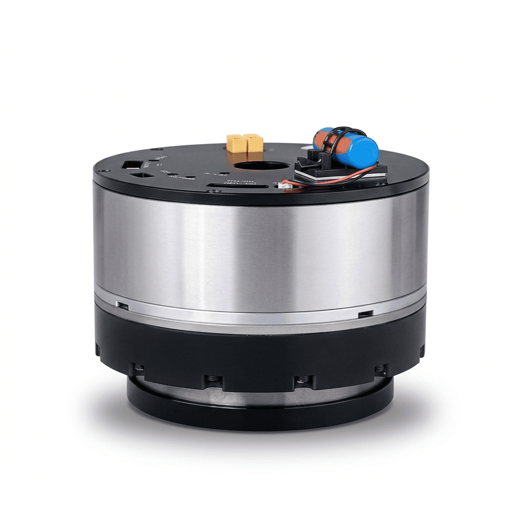
48V vs 24V Robotic Joint Modules: Power Density and Sourcing Guide
Compare 48V vs 24V robotic joint modules for power density, thermal limits, safety scope, RFQ checks, and sourcing decisions before supplier review starts.