
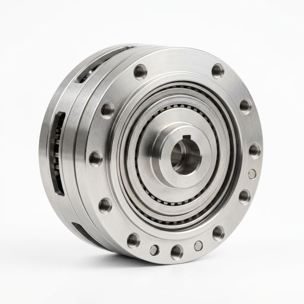
Dual vs Single Encoder Robot Joint Modules: Procurement Guide
Compare dual vs single encoder robotic joint modules for cobots and humanoids, with supplier questions, trade-offs, sourcing limits, and RFQ guidance.
When specifying a robotic joint module, the choice between a single-encoder and dual-encoder architecture dramatically impacts the cost, safety certification, and real-world precision of your robot.
Inquiries from engineering and procurement teams often focus heavily on motor torque and gearbox ratios. However, as collaborative robots (cobots) and humanoids require safer, more compliant motion, the feedback loop—dictated by the encoder setup—has become the primary bottleneck for system performance.
This guide is written to help buyers and system architects decide when to pay the premium for a dual-encoder module and when a single-encoder design is sufficient.
Scope and update note: Updated July 19, 2026 for global OEM sourcing teams comparing integrated servo joint modules that use harmonic, cycloidal, or planetary reduction. It is a procurement and engineering screening guide, not a substitute for project-specific safety validation, servo tuning, or certification review by a qualified safety integrator.
If you are still building the supplier shortlist, start with the robotic joint module product portfolio and use this article to decide which encoder questions should appear in your RFQ.
Engineering Visualization: Single vs. Dual Loop Architecture
The "Blind Spot" in a single encoder system occurs because the controller cannot detect deflection, backlash, or wear occurring inside the gearbox. Dual encoders close the loop directly at the output flange.
The Single Encoder Baseline
In a standard single-encoder robotic joint, the feedback sensor is mounted directly on the rear shaft of the motor.
How it works: The controller reads the motor's position and speed, then calculates the output shaft's position by dividing by the gear ratio (e.g., 100:1).
The Limitation: This math assumes the gearbox is perfectly rigid. In reality, harmonic drives and cycloidal gears possess mechanical compliance (spring-like behavior) and hysteresis. If an external force pushes against the robot arm, the gearbox flexes. The motor encoder will not detect this micro-movement, resulting in positioning errors at the Tool Center Point (TCP).
When to specify single encoders
- Cost-sensitive AGV/AMR wheels: Absolute millimeter precision is handled by LiDAR/SLAM, not the wheel odometry.
- Rigid industrial robots: Heavy-cast arms using highly rigid planetary or cycloidal drives where structural deflection is minimal.
- Educational and maker platforms: Where functional safety certifications are not required.
The Dual Encoder Advantage
Dual-encoder modules feature a second, high-resolution absolute encoder mounted directly on the output flange (after the gearbox).
Overcoming Compliance: By comparing the motor encoder (fast, high-resolution for commutation and velocity loops) with the output encoder (absolute position of the load), the servo drive can calculate and actively compensate for gearbox deflection. This is called "dual-loop control."
Safety & ISO Compliance: For collaborative robots, dual encoders are often used as part of the redundancy and diagnostic coverage needed for higher Performance Level targets under safety standards. If a gear tooth breaks or the output shaft shears, the motor encoder can continue spinning normally. The output encoder detects the discrepancy at the load side and gives the safety controller evidence for a controlled stop or Safe Torque Off (STO) response, depending on the certified architecture.
When to specify dual encoders
- Humanoids and Legged Robots: Requires force-control and impedance control to absorb shock when walking; dual encoders enable precise torque estimation without external load cells.
- Cobots and Medical Arms: ISO 10218-1/2 and ISO/TS 15066 compliance demands robust fault detection and power/force limiting (PFL) capabilities.
- High-Precision Machining: Where backlash and hysteresis must be mathematically zeroed out at the tool tip.
Direct Comparison: Single vs. Dual Encoder Modules
| Decision Metric | Single Encoder Module | Dual Encoder Module |
|---|---|---|
| BOM Cost Impact | Baseline | +15% to +35% (hardware + advanced drive) |
| Backlash/Hysteresis | Uncompensated (blind) | Actively compensated via dual-loop firmware |
| Functional Safety (ISO 13849) | Difficult to achieve high PL without external sensors | Supports PLd / PLe redundancy requirements |
| Force Estimation | Highly inaccurate due to friction | Excellent (calculates force via deflection delta) |
| Control Complexity | Standard PID loops | Requires complex dual-loop tuning and filtering |
| Physical Dimensions | Most compact | Slightly longer axial length to house secondary PCB |
| Wiring & Connectors | Standard | Requires higher pin-count or dense serial comms |
Procurement Checklist: Qualifying an OEM Supplier
If you have decided that your program requires dual encoders, your procurement and engineering teams must verify the supplier's actual integration capability. Adding a second sensor is easy; processing the data correctly is difficult.
Ask these questions during the RFQ phase:
- Are both encoders absolute? (Prefer battery-less multi-turn absolute encoders on the output to avoid complex homing routines after power loss).
- Does the onboard drive support dual-loop control internally? (If the module only passes two raw encoder signals over EtherCAT, your main controller will be burdened with massive computation overhead).
- How is the output encoder calibrated? (Ask for the OEM's factory calibration procedure. The eccentricity of the output bearing can ruin encoder accuracy if not mapped).
- What is the transmission protocol? (High-speed protocols like BiSS-C or EnDat 2.2 are required to minimize latency between the two sensors).
For a faster commercial next step, compare candidate families in the product portfolio, then send torque, speed, bus, and encoder requirements through the Contact / RFQ page. This keeps the encoder decision tied to real lead time, connector, firmware, and certification constraints instead of a standalone component preference.
FAQ
Q: Can we just use a better, zero-backlash gearbox and stick to a single encoder? A: Even "zero-backlash" harmonic drives have torsional compliance. Under heavy payloads, the flex in the flexspline will cause positioning errors that a single motor encoder cannot see. If your application requires high stiffness, dual encoders act as "electronic stiffness."
Q: Does a dual encoder module eliminate the need for a 6-axis force/torque sensor? A: For many cobot applications, yes. By measuring the wind-up between the motor encoder and the output encoder, the controller can estimate joint torque accurately enough for collision detection and hand-guiding, saving thousands of dollars on external load cells.
Q: Are there physical size penalties for dual encoders? A: Historically, yes. However, modern modules use highly integrated magnetic ring encoders or hollow-shaft optical encoders that add only 5–10mm to the total axial length of the joint module.
Sources & References
To dive deeper into the control theory and safety standards governing these architectures, refer to the following source material. Standards pages can change by region and edition, so confirm the active edition during the compliance review.
- ISO 10218-1:2025 - Robots and robotic devices — Safety requirements for industrial robots, Part 1. Use it as the starting point for manufacturer-side robot safety requirements. ISO 10218-1:2025
- ISO/TS 15066:2016 - Collaborative robot application guidance, including power and force limiting considerations. ISO/TS 15066:2016
- HEIDENHAIN Robotics Encoder Resources - Manufacturer application material on rotary encoders and feedback architectures used in advanced robotics. HEIDENHAIN robotics resources
- Kollmorgen Dual-Loop Feedback Guidance - Servo supplier guidance explaining why a load-side feedback device is used to compensate compliance, backlash, and load disturbances. Dual-loop feedback guidance
Need Support with Joint Module Selection?
Selecting the right sensing architecture early in your EVT phase prevents costly firmware rewrites and mechanical redesigns down the road.
If your team is evaluating joint modules for a new cobot, humanoid, or custom automation platform, contact our engineering team to discuss torque profiles, communication buses, and encoder configurations.
- Email: [email protected]
- WhatsApp: +86 18857971991
Categories
More Posts
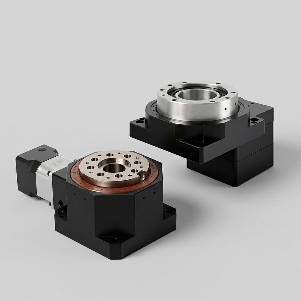
Hollow-Shaft vs Solid-Shaft Robot Joint Modules: A Sourcing Guide (2026)
An engineering and procurement guide to evaluating hollow-shaft versus solid-shaft robotic joint modules for humanoid, cobot, and industrial robot arms.

Functional Safety (STO & SBC) in Integrated Joint Modules: A Procurement Guide
Evaluate functional safety, STO, and SBC requirements for robotic joint modules, with sourcing checks for engineers and procurement teams before a vendor RFQ.
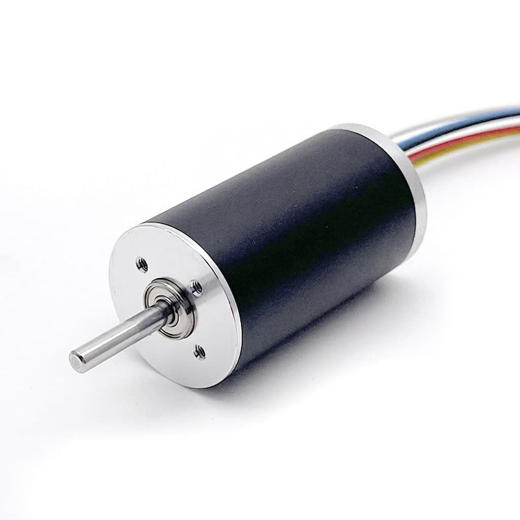
Frameless Torque Motor Guide: Outrunner vs Inrunner for Robotic Joints
A practical comparison of outrunner and inrunner frameless torque motors for cobot, humanoid, and precision motion applications.