
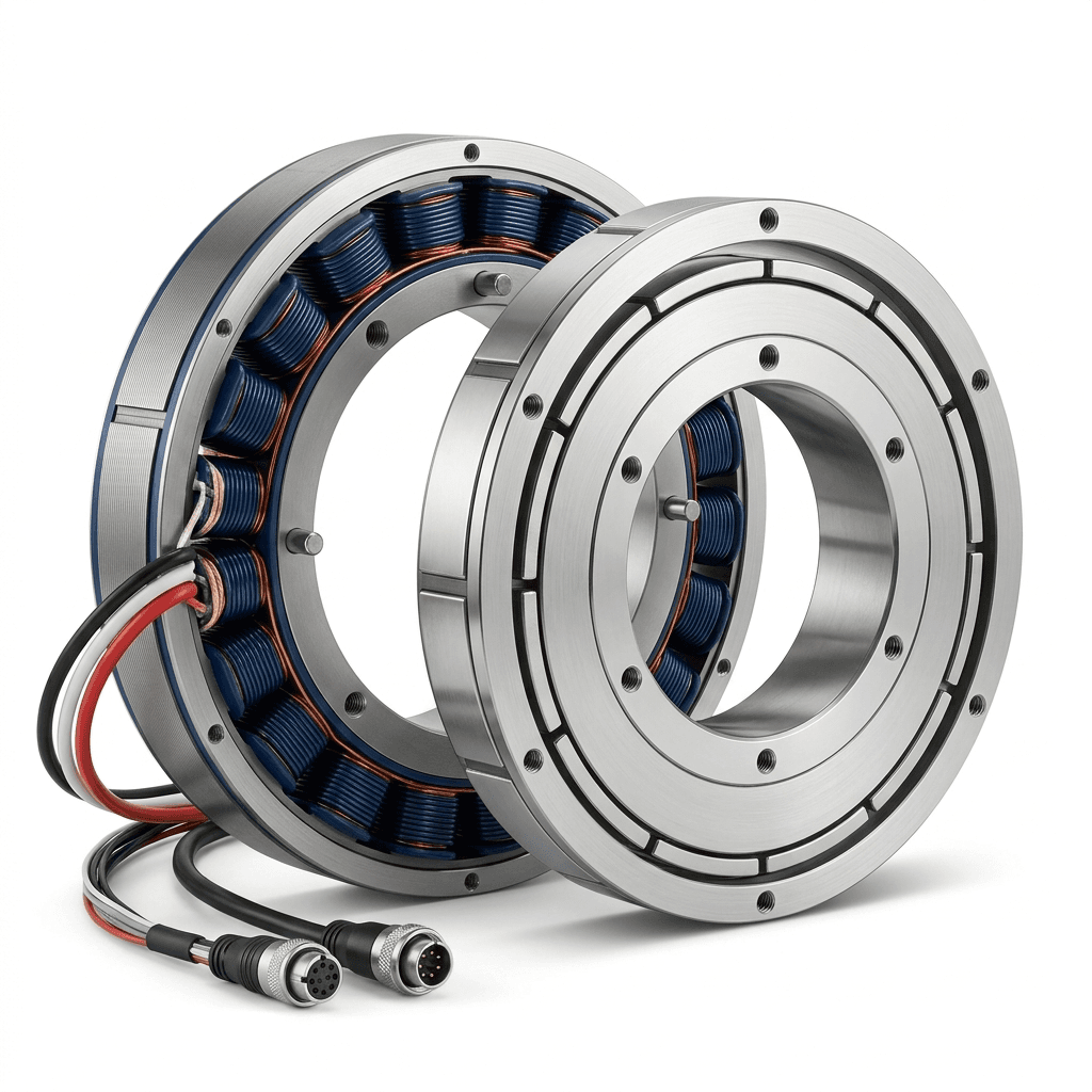
Frameless Torque Motor Guide: Outrunner vs Inrunner for Robotic Joints
A practical comparison of outrunner and inrunner frameless torque motors for cobot, humanoid, and precision motion applications.
Frameless torque motor selection looks simple on paper and becomes complicated on the bench. Most teams can list the target torque, but fewer teams lock the thermal and control assumptions early enough.
For most programs, the first decision is architecture: outrunner or inrunner.
I usually frame it this way: pick the control behavior first, then pick the motor architecture that can support it.
Outrunner vs inrunner: practical differences
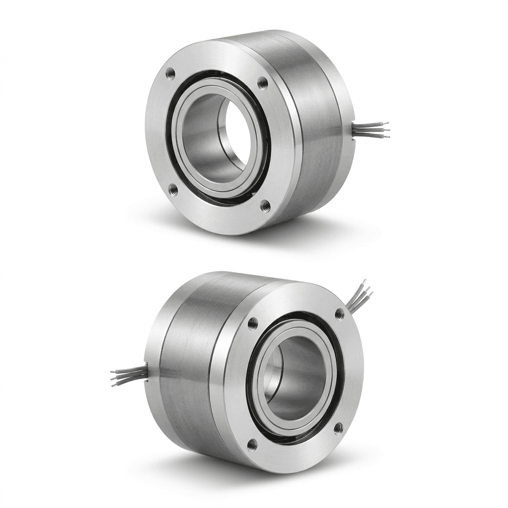
Outrunner: larger effective torque radius, often favorable for higher torque density in compact envelopes.Inrunner: lower rotor inertia, usually better for fast dynamic response and higher bandwidth control.
The right answer depends on your joint function, not just a headline torque number.
Parameters buyers must compare on one sheet
Request a normalized comparison with these fields:
Kt(torque constant) and usable current windowKvand rated speed range- Phase resistance/inductance for controller matching
- Rotor inertia for response and stability tuning
- Cogging torque profile at low speed
- Thermal resistance and allowable continuous temperature rise
Engineering Visualization: Continuous vs. Peak Torque Envelope
Notice how the continuous zone (blue) drops off sharply due to winding thermal limits, while the peak zone (orange) is constrained by back-EMF and driver voltage saturation at high speeds. Your RFQ must specify exactly where your load falls on this curve.
Without this set, outrunner vs inrunner decisions are mostly guesswork.
If a supplier gives only one “rated torque” value without the test condition, ask for a corrected sheet before continuing.
What advanced buyers compare beyond torque
Experienced teams check:
- Cogging behavior at low speed and micro-motion
- Thermal path and continuous torque stability
- Rotor inertia impact on control tuning
- Mechanical integration tolerance and assembly repeatability
- Manufacturability at pilot and volume stage
Ignoring these factors creates late-stage redesign costs.
Practical architecture mapping
Use this as a first-pass rule:
| Design priority | Outrunner tendency | Inrunner tendency |
|---|---|---|
| Peak torque in tight radial envelope | Strong | Conditional |
| High dynamic response and control bandwidth | Conditional | Strong |
| Lower reflected inertia sensitivity | Conditional | Strong |
| Compact coaxial stack with reducer integration | Strong | Conditional |
Then validate with prototype data, not only catalog interpretation.
Catalog numbers are useful for shortlisting, not for final release decisions.
Typical application mapping
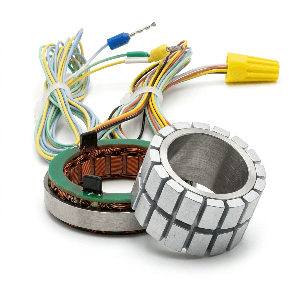
Outrunner-frameless concepts are commonly evaluated for:
- Payload-oriented joints with constrained outer envelope
- Direct-drive or low-ratio designs prioritizing peak output
Inrunner-frameless concepts are commonly evaluated for:
- High-dynamic joints with strict response targets
- Applications sensitive to reflected inertia and control smoothness
Test and acceptance package to require from suppliers
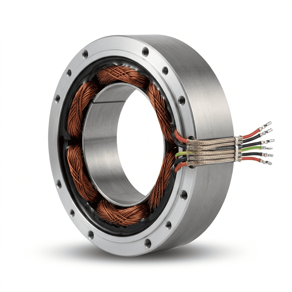
Before supplier down-selection, request:
- Torque-speed and efficiency curves with test fixture definition.
- Thermal rise report at defined duty cycle and ambient conditions.
- Cogging waveform data in low-speed region.
- Rotor inertia measurement method and tolerance band.
- Batch-level variation statement for winding and magnet assembly.
If the supplier cannot provide repeatable test context, data quality is weak.
OEM sourcing checkpoints
Before final supplier decision, request:
- Test method definitions for torque, thermal rise, and cogging.
- Material and winding consistency controls.
- Matching recommendations with gearbox, encoder, and driver.
- Engineering support process for design iteration and NPI.
A supplier that can support the full module stack reduces interface risk.
Common failure modes to screen early
During sample validation, look for:
- Thermal drift: NdFeB magnets typically lose 0.11% of residual flux (Br) per °C rise. A 60°C rise can cause a 6-7% torque drop, requiring the controller to push more current, creating a thermal runaway loop.
- Excess low-speed ripple (Cogging): Causes unacceptable end-effector jitter in surgical or precision assembly tasks.
- Bearing preload decay: Assembly tolerance drift that changes bearing preload feel after high-impact stress.
- Harness strain: Lead wire fatigue under repeated cyclic articulation inside the joint cavity.
Quantitative FMEA (Failure Mode and Effects Analysis) Snapshot:
| Failure Mode | Root Cause | OEM Detection Method |
|---|---|---|
| Cogging Torque > 2% of Peak | Poor stator-rotor concentricity or stamping burrs | Low-speed back-EMF mapping on dynamometer |
| Premature Thermal Saturation | Insufficient potting compound or epoxy voids | Thermocouple embedding during 4-hour S1 nominal load test |
| Demagnetization | Over-current during stall combined with high ambient | Back-EMF constant (Ke) check before and after stall-test |
Early detection here can prevent expensive mechanical redesign in pilot phase.
I strongly recommend doing these checks before locking custom tooling. It is the cheapest point in the schedule to fix architecture errors.
Method used in this architecture comparison
This article uses a buyer-side integration method instead of catalog-only ranking:
- Normalize electrical constants (
Kt,Kv, resistance, inductance) on one sheet. - Compare inertia and low-speed smoothness behavior under the same load fixture.
- Validate thermal stability under your real duty cycle, not no-load marketing curves.
- Score manufacturability and consistency risk before commercial negotiation.
This order prevents “high peak torque but low project reliability” decisions.
Practical test plan template (sample stage)
| Test block | What to record | Release threshold example |
|---|---|---|
| Low-speed smoothness | Cogging waveform + ripple trend | No abnormal ripple spikes near control target band |
| Dynamic response | Step response and settling behavior | Stable tuning margin under expected inertia |
| Thermal stability | Temperature rise vs continuous load | No derating surprise in planned ambient range |
| Assembly repeatability | Concentricity and preload check across samples | Variation stays inside agreed mechanical tolerance |
| Stack integration | Encoder-driver-gearbox interaction notes | No unresolved interface ambiguity before pilot |
Boundaries and assumptions
- This guide compares architecture direction, not brand ranking.
- Final choice must be validated with your own fixture, controller, and duty profile.
- If your project includes strict human-interaction safety constraints, add force-control and compliance checks beyond this motor-level comparison.
Source references
- Kollmorgen frameless motor overview: kollmorgen.com
- Celera Motion frameless motor resources: celeramotion.com
- IEC standards portal (for standards discovery and verification): iec.ch
Last reviewed: 2026-05-25
Related pages
Inquiry
For frameless torque motor OEM projects and custom joint integration:
- Email: [email protected]
- WhatsApp: +86 18857971991
Categories
More Posts
Functional Safety (STO & SBC) in Integrated Joint Modules: A Procurement Guide
Evaluate functional safety, STO, and SBC requirements for robotic joint modules, with sourcing checks for engineers and procurement teams before a vendor RFQ.

Hollow-Shaft vs Solid-Shaft Robot Joint Modules: A Sourcing Guide (2026)
An engineering and procurement guide to evaluating hollow-shaft versus solid-shaft robotic joint modules for humanoid, cobot, and industrial robot arms.
Dual vs Single Encoder Robot Joint Modules: Procurement Guide
Compare dual vs single encoder robotic joint modules for cobots and humanoids, with supplier questions, trade-offs, sourcing limits, and RFQ guidance.