Functional Safety (STO & SBC) in Integrated Joint Modules: A Procurement Guide
Evaluate functional safety, STO, and SBC requirements for robotic joint modules, with sourcing checks for engineers and procurement teams before a vendor RFQ.
For years, robotic safety systems relied on centralized cabinets filled with bulky contactors, complex discrete wiring harnesses, and standalone safety programmable logic controllers (PLCs). However, the rapid proliferation of collaborative robots (cobots), mobile manipulators (MoMos), and humanoid robots has fundamentally shifted the paradigm. Today, achieving compliance with strict safety standards without compromising on torque density or weight demands that functional safety—specifically Safe Torque Off (STO) and Safe Brake Control (SBC)—be embedded directly into the integrated joint module itself.
But not all "safety-ready" joint modules are created equal. If you are an engineering lead or a procurement manager evaluating a new robotic platform, distinguishing between a truly certified SIL 3 / PL e integrated module and a non-certified drive claiming "safety features" is critical. Relying on vague marketing claims can lead to delayed product launches, failed safety audits, and catastrophic failures in the field.
This guide breaks down the engineering requirements, architectural differences, and sourcing realities of STO and SBC in integrated robotic joint modules, providing actionable insights for your next vendor evaluation.
Last reviewed: July 26, 2026. Scope: global OEM and integrator sourcing for collaborative robots, mobile manipulators, humanoids, personal-care robots, and enclosed industrial robot cells. This guide is not a substitute for a project-specific risk assessment, third-party certification review, or legal interpretation of local machine-safety requirements.
Quick Answer for Sourcing Teams
When sourcing joint modules for a collaborative or autonomous platform, prioritize pre-certified modules with integrated dual-channel STO and SBC if your application requires human-robot collaboration (ISO 10218 / ISO/TS 15066) or mobile autonomy (ISO 13482). These modules significantly reduce system-level certification time, eliminate the need for heavy external safety contactors, and reduce wiring complexity across rotating joints. However, if you are building a fully enclosed industrial robot operating behind physical light curtains, standard joint modules paired with centralized safety cabinets may still offer a lower component cost. Always verify the module's Diagnostic Coverage (DC), Mean Time to Dangerous Failure (MTTFd), and hardware interlocking mechanisms before proceeding with an RFQ.
1. What are STO and SBC in the Context of Integrated Modules?
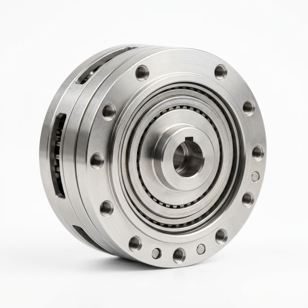
Functional safety in robotics is about ensuring that the system fails predictably and safely. In the context of a robotic joint module—which typically combines a frameless torque motor, harmonic or cycloidal gearing, dual encoders, a holding brake, and a servo drive—functional safety functions intervene at the hardware level to prevent hazardous motion.
Safe Torque Off (STO)
Safe Torque Off (STO) is the foundational safety function. According to IEC 61800-5-2, STO ensures that no torque-generating energy can continue to act upon the motor. In an integrated joint module, triggering the STO function physically disconnects the power to the motor's gate drivers (often via redundant, dual-channel hardware circuits), regardless of the software commands being sent by the main robot controller.
- The critical distinction: STO does not mean the power supply to the entire joint is cut off. The control logic, encoders, and communication bus (like EtherCAT) remain active. This allows the system to monitor the joint's position while in a safe state, enabling a rapid restart once the safety zone is cleared, without requiring a complete system reboot or homing routine.
Safe Brake Control (SBC)
While STO prevents the motor from generating torque, it does not stop a moving load. If an STO is triggered on a vertical robot axis carrying a heavy payload, gravity will cause the arm to collapse, creating a severe hazard. This is where Safe Brake Control (SBC) becomes mandatory. SBC safely controls an external holding brake. In an integrated joint module, SBC is inextricably linked with STO. When STO is triggered, the SBC circuit safely removes power from the electromagnetic brake coil, allowing the mechanical springs to engage the brake pads and halt the load. Like STO, SBC must be implemented redundantly and must withstand single-point hardware failures.
Engineering Visualization: STO and SBC Activation Flow
Fig 1: Dual-channel safety signals bypassing the main microcontroller to directly disable gate drivers (STO) and engage mechanical brakes (SBC).
2. The Cost of Non-Compliance vs. Pre-Certified Joints
Historically, sourcing teams might have balked at the premium price of a TÜV-certified integrated joint module with native STO/SBC, opting instead for a standard servo module and external safety relays. However, the total cost of ownership (TCO) and the burden of system-level certification heavily favor the integrated approach in modern robotic architectures.
When a robot manufacturer uses non-certified joints, the burden of proving PL e (Performance Level e) or SIL 3 (Safety Integrity Level 3) falls entirely on the OEM's engineering team. They must perform exhaustive Failure Mode and Effects Analysis (FMEA), calculate MTTFd (Mean Time to Dangerous Failure), and often hire third-party auditors to validate the entire electrical cabinet.
By sourcing a pre-certified joint module, the OEM inherits the supplier's certification for the actuator subsystem. The engineering team only needs to validate the integration and the safety logic, slashing certification timelines by months.
Component Comparison: Discrete Safety vs. Integrated STO/SBC
| Evaluation Criteria | Discrete External Safety (Contactors/Relays) | Pre-Certified Integrated STO/SBC Module | Procurement & Engineering Impact |
|---|---|---|---|
| System Weight | High. Requires heavy safety contactors in base cabinet. | Low. Safety logic is miniaturized on the module's PCB. | Critical for MoMos and humanoids where every gram reduces battery life. |
| Wiring Complexity | Very High. Requires thick power cables routed back to the cabinet for every joint. | Low. Utilizes a shared DC bus and a lightweight logic cable for safety signals (or FSoE). | Reduces harness failure rates, slip-ring complexity, and assembly time. |
| Recovery Latency | Slow. Removing main power requires a full system boot-up and re-homing upon restart. | Fast. Logic power remains active. Position data is retained for immediate operation resume. | Dramatically improves Overall Equipment Effectiveness (OEE) in factories. |
| SBC Implementation | Hard to synchronize externally. Gravity drops may occur if contactors lag. | Highly synchronized in hardware. Brake engages immediately upon STO trigger. | Prevents tooling damage and operator injury from collapsing arms. |
| Component Cost | Lower per joint, but high hidden cabinet costs. | Higher upfront cost per joint module. | Procurement must evaluate TCO, not just the BOM cost of the actuator. |
| Certification Burden | OEM is fully responsible for proving the safety chain. | OEM inherits the module's TÜV/UL safety certificates. | Reduces time-to-market by 3-6 months and lowers consulting fees. |
3. Dual-Encoder Architectures and Diagnostic Coverage
A critical requirement for achieving SIL 3 / PL e in a joint module is high Diagnostic Coverage (DC)—the ability of the system to detect dangerous faults before they lead to an accident. In high-performance joint modules, this is primarily achieved through a Dual-Encoder Architecture.
Typically, an integrated joint module features:
- A motor-side encoder (high resolution, incremental or absolute, used for field-oriented control and velocity loops).
- An output-side encoder (absolute, placed after the harmonic or cycloidal gear, used for precise joint positioning).
From a functional safety perspective, the onboard safety microcontroller continuously cross-checks the data from both encoders. By knowing the exact gear ratio, the safety processor can detect discrepancies. If the gear fails (e.g., ratcheting or tooth breakage), or if an encoder slips, the expected relationship between the motor angle and the output angle is violated. The safety processor immediately triggers the STO and SBC circuits.
When evaluating suppliers, engineers must ask whether the dual encoders are truly independent and whether they are routed through separate input channels on the safety processor. If both encoders share a single multiplexer or power rail that constitutes a single point of failure, the module cannot achieve a high safety rating.
4. Procurement Checklist: Evaluating Safety-Rated Joint Modules
To avoid costly redesigns late in the development cycle, use this checklist during the Request for Information (RFI) and vendor evaluation phase:
- Request Official Certificates: Do not accept claims of "designed to meet SIL 3." Request the actual TÜV Rheinland, UL, or Exida certificate verifying ISO 13849-1 (PL) or IEC 61508 (SIL) compliance.
- Verify Dual-Channel Architecture: Confirm that the STO input accepts dual-channel (OSSD) signals and that the internal cutoff mechanism is physically redundant.
- Check SBC Integration: Ensure that triggering the STO input automatically and safely drops power to the holding brake (SBC). Ask for the timing diagram showing the delay between STO and SBC.
- Request the Safety Manual: A certified product must come with a dedicated Safety Reference Manual detailing the MTTFd, DC, and specific wiring instructions. If the vendor cannot provide this, they are not ready for production.
- Evaluate Network Safety (FSoE/PROFIsafe): For advanced systems, check if the module supports safety over the fieldbus (e.g., Fail Safe over EtherCAT). This can completely eliminate discrete safety wiring.
- Assess Brake Holding Torque: The SBC is useless if the brake cannot hold the maximum dynamic load of the robot arm. Verify the static holding torque rating and the emergency stop degradation profile.
5. Risk & Trade-offs: When is Integrated Safety Overkill?
While integrated STO/SBC is the gold standard for modern collaborative robotics, it is not universally necessary. Understanding the boundaries of application can save significant procurement budget.
When to Avoid the Premium of Integrated Safety:
- Fully Enclosed Industrial Cells: If you are building a traditional, heavy-duty SCARA or 6-axis robot that operates entirely behind physical fences and light curtains, humans are never in the workspace while the robot has power. In this scenario, centralized cabinet-based safety contactors that cut power to the entire drive rack are sufficient and far more cost-effective.
- Low-Risk Educational/Research Platforms: For university lab robots or small desktop arms where the payload and speeds are too low to cause injury (and ISO 10218 compliance is not strictly required), standard uncertified joint modules are appropriate.
- Strict Size/Weight Constraints (Micro-Robotics): The redundant circuits, dual encoders, and safety microprocessors add physical volume to the joint. In miniature robotic fingers or surgical manipulators, it may be physically impossible to integrate STO circuits directly into the actuator housing.
6. Frequently Asked Questions (FAQ)
Q: Can we achieve PL d or PL e using a single encoder in our joint module? A: It is extremely difficult and rare. While PL c can sometimes be achieved with a highly reliable single absolute encoder and rigorous software diagnostics, PL d and PL e generally require hardware redundancy (Category 3 or 4 architecture). Dual encoders are the industry standard for meeting these higher diagnostic coverage requirements.
Q: If a joint module has STO, does it automatically mean it has Safe Stop 1 (SS1) or Safe Stop 2 (SS2)? A: No. STO and SBC are hardware-level unpowered safe states (Safe Stop 0 / SS0). SS1 (controlled deceleration before STO) and SS2 (controlled deceleration followed by Safe Operating Stop) require sophisticated safety-rated motion controllers. While the joint module's STO is the foundational actuator for these functions, the intelligence usually resides in a higher-level safety PLC unless the module features an advanced integrated safety motion controller.
Q: What is the difference between an electromagnetic holding brake and a Safe Brake? A: An electromagnetic holding brake is a mechanical component. "Safe Brake Control" (SBC) refers to the electronic control circuit that guarantees power is removed from that brake reliably, even in the event of a single hardware fault. You need both a robust mechanical brake and an SBC circuit to ensure safety.
Q: We are developing a quadruped robot. Do we need STO/SBC on the leg joints? A: It depends on the operating environment and risk assessment. If the quadruped operates in public spaces (e.g., delivery, inspection in occupied facilities), safety standards like ISO 13482 for personal care robots apply, making integrated STO highly recommended to instantly kill torque if a human is struck. However, SBC (brakes) on quadruped legs are often omitted to save weight, as the robot can safely "collapse" to the ground without causing severe crushing hazards compared to a heavy robotic arm.
7. Next Steps for Engineering and Sourcing
The transition from discrete safety components to integrated functional safety within the joint module represents a major leap in robotic design efficiency. For procurement teams, it shifts the focus from buying cheap motors to sourcing highly sophisticated, pre-certified mechatronic subsystems that drastically reduce time-to-market.
If your engineering team is currently defining the architecture for a new collaborative robot, mobile manipulator, or medical device, do not leave safety certification as an afterthought.
Ready to evaluate safety-rated hardware? Explore our latest generation of EtherCAT / CANopen Integrated Joint Modules, featuring native dual-channel STO, SBC, and compatibility planning for safety-capable fieldbus architectures. Contact our application engineering team today with your specific payload and reach requirements for a customized thermal and safety assessment.
8. Sources and References
- International Organization for Standardization (ISO). ISO 10218-1:2011 Robots and robotic devices — Safety requirements for industrial robots — Part 1: Robots. Available at: ISO Official Site. Used for industrial robot safety context and risk-reduction expectations.
- International Electrotechnical Commission (IEC). IEC 61800-5-2:2016 Adjustable speed electrical power drive systems — Part 5-2: Safety requirements — Functional. Available at: IEC Webstore. Used for drive-level safety functions including STO and brake-control-related requirements.
- International Organization for Standardization (ISO). ISO 13482:2014 Robots and robotic devices — Safety requirements for personal care robots. Available at: ISO Official Site. Used for mobile/personal-care robot scope where human proximity changes the sourcing threshold.
- International Organization for Standardization (ISO). ISO 13849-1:2015 Safety of machinery — Safety-related parts of control systems — Part 1: General principles for design. Available at: ISO Official Site. Used for PL, category, MTTFd, and diagnostic coverage language in supplier evidence requests.
- EtherCAT Technology Group. Safety over EtherCAT. Available at: ethercat.org. Used for fieldbus safety context when evaluating FSoE/black-channel safety integration.
Categories
More Posts
Dual vs Single Encoder Robot Joint Modules: Procurement Guide
Compare dual vs single encoder robotic joint modules for cobots and humanoids, with supplier questions, trade-offs, sourcing limits, and RFQ guidance.

Robot Joint Module Thermal Management & Derating Guide
A comprehensive guide for engineers and procurement teams on understanding thermal derating, continuous torque limits, and heat mitigation strategies in robotic joint modules.
48V vs 24V Robotic Joint Modules: Power Density and Sourcing Guide
Compare 48V vs 24V robotic joint modules for power density, thermal limits, safety scope, RFQ checks, and sourcing decisions before supplier review starts.